Infrared imaging system

a technology of infrared imaging and infrared radiation, which is applied in the direction of radiation control devices, instruments, optical radiation measurement, etc., can solve the problems of insufficient infrared radiation amount, inability to use far-infrared imaging systems with synthetic resin lenses, and insufficient transmittance of synthetic resin materials, so as to reduce the sag of the surface, reduce the sag of the lens, and reduce the refractive power of the exit surface surface surface surface surface surface surface surface surface surface surface surface surface surface surface surface surface surface surface surface surface surface surface surface surface surface surface surface surface surface surface surface surface surface surface surface surface surface surface surfa

Active Publication Date: 2015-07-23
TELEDYNE FLIR LLC +1
View PDF3 Cites 2 Cited by
  • Summary
  • Abstract
  • Description
  • Claims
  • Application Information

AI Technical Summary

Benefits of technology

[0007]In the infrared imaging system according to an embodiment of the present disclosure, for the upper ray, the entry surface and the exit surface have positive refractive power while θ changes from 0 to the maximum value for the infrared imaging system, and the refractive power increases with increase of θ. As a result, the refractive power of the exit surface is relatively reduced, and therefore, the lens thickness can be reduced by reducing the SAG of the surface. Absorption of infrared rays can be reduced by reducing the lens thickness.
[0008]In the infrared imaging system according to an embodiment of the present disclosure, for the lower ray, the entry surface and the exit surface have positive refractive power when θ is in a lower range, and therefore, the focal length of the lens becomes shorter and the F-number becomes smaller. With increase of θ, the refractive power of the entry surface becomes negative, and the absolute value of the negative refractive power increases. As a result, the converging angle becomes greater for a greater value of θ.
[0009]In the infrared imaging system according to an embodiment of the present disclosure, the F-number on the optical axis is 1.4 or smaller. Further, absorption of infrared rays is reduced by reducing the thickness of the lens made of synthetic resin. Accordingly, the infrared imaging system according to an embodiment of the present disclosure is capable of obtaining a sufficient amount of light using a lens made of synthetic resin.

Problems solved by technology

In general, however, transmittance of a synthetic resin material for far-infrared rays is lower than transmittance of the synthetic resin material for visible light, and therefore a synthetic resin lens which used for visible light imaging systems typically cannot be used for far-infrared imaging systems.
In other words, if a synthetic resin lens that is used for visible light imaging systems is coopted for use with far-infrared imaging systems, the amount of infrared radiation becomes insufficient because of absorption of far-infrared rays of the synthetic resin lens.
Accordingly, lenses of conventional far-infrared imaging systems typically employ relatively expensive materials that absorb less infrared radiation, such as germanium and various chalcogenides, or other materials that can only be shaped by machining and therefore require higher manufacturing costs, such as silicon (e.g., see JP2002-014283 and JP11-326757, where are hereby incorporated by reference in their entirety).

Method used


Image

  • Infrared imaging system
  • Infrared imaging system
  • Infrared imaging system

Examples


example 1

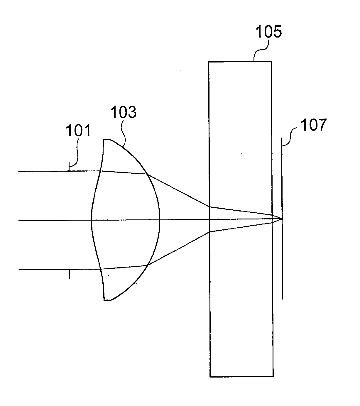
[0067]FIG. 7 shows a construction of an infrared imaging system according to Example 1. The infrared imaging system includes, from the object side to the image side, an aperture 1101, a lens 1103, a protective plate 1105 and an image surface 1107. The entry surface of the lens 1103 (the object side surface) is shaped such that the surface is convex to the object side at least in the paraxial area. The straight line which passes through the center of the aperture 1101 and the center of the lens 1103 and is perpendicular to the plane of the aperture 1101 is designated as the optical axis.

[0068]Along the optical axis, the distance between the aperture 1101 and the entry surface of the lens 1103 is represented as t0, the thickness of the lens 1103 at the center is represented as t1, and the distance between the lens 1103 and the image surface 1107 is represented as t2. The thickness of the lens 1103 in the optical axis direction at the periphery of the effective aperture is represented ...

example 2

[0084]FIG. 12 shows a construction of an infrared imaging system according to Example 2. In the infrared imaging system, from the object side to the image side an aperture 2101, a lens 2103, a protective plate 2105 and an image surface 2107 are disposed. The entry surface of the lens 2103 (the object side surface) is shaped such that the surface is convex to the object side in the paraxial area. Although not shown in FIG. 12, the exit surface of the lens 2103 is shaped as a Fresnel lens. The straight line which passes through the center of the aperture 2101 and the center of the lens 2103 and is perpendicular to the plane of the aperture 2101 is designated as the optical axis.

[0085]Along the optical axis, the distance between the aperture 2101 and the entry surface of the lens 2103 is represented as t0, the thickness of the lens 2103 at the center is represented as t1, and the distance between the lens 2103 and the image surface 2107 is represented as t2. The thickness of the lens 2...

example 3

[0100]FIG. 17 shows a construction of an infrared imaging system according to Example 3. In the infrared imaging system, from the object side to the image side a first lens 3109, an aperture 3101, a second lens 3103, a protective plate 3105 and an image surface 3107 are disposed. The entry surface of the second lens 3103 (the object side surface) is shaped such that the surface is convex to the object side in the paraxial area. Although not shown in FIG. 17, the exit surface of the second lens 3103 is shaped as a Fresnel lens. The straight line which passes through the center of the aperture 3101 and the center of the second lens 3103 and is perpendicular to the plane of the aperture 3101 is designated as the optical axis.

[0101]Along the optical axis, the thickness of the first lens 3109 at the center is represented as ts1, the distance between the exit side of the first lens 3109 and the aperture 3101 is represented as ts2, the distance between the aperture 3101 and the entry surfa...


PUM


Abstract

An infrared imaging system used for infrared rays of wavelength of 5 micrometers or greater, the system including, from the object side to the image side, an aperture, a lens made of synthetic resin and an imaging element, the object side surface of the lens being convex to the object side in the paraxial area, wherein F-number of the system is 1.4 or smaller.

Description

TECHNICAL FIELD[0001]One or more embodiments of the invention relate generally to infrared imaging and more particularly, for example, to systems and methods for providing lenses for infrared imaging systems.BACKGROUND ART[0002]In thermography, nightscopes, security systems, and the like, imaging systems for electromagnetic waves of the wavelength range from several to several tens of micrometers are used. The electromagnetic waves of the above-described wavelength range are referred to as far-infrared rays. In imaging systems that image far-infrared rays, data of far-infrared rays are captured by an imaging element in which infrared detecting elements are arranged in array. Conventional infrared detecting elements include a thermopile type which utilizes electromotive force generated by a temperature change caused by collected infrared rays, a bolometer type which utilizes a change in electric resistance generated by a temperature change, a pyroelectric type which utilizes a change...

Claims


Application Information

Patent Timeline
Patent Type & Authority Applications(United States)
IPC IPC(8): H01L27/146G01J1/04G02B3/04
CPCH01L27/14601G01J1/0411G02B3/04G02B13/14G02B3/08
Inventor FUJIMURA, KAYOKOIKEDA, KATSUMOTOSEKI, DAISUKE
Owner TELEDYNE FLIR LLC
Why Eureka
Try Eureka