Power Steering System Hydraulic Pump

a technology of hydraulic pump and power steering system, which is applied in the direction of rotary/oscillating piston pump components, machines/engines, liquid fuel engines, etc., and can solve problems such as processing effor

Active Publication Date: 2009-05-14
TRW AUTOMOTIVE GMBH
View PDF9 Cites 2 Cited by
  • Summary
  • Abstract
  • Description
  • Claims
  • Application Information

AI Technical Summary

Benefits of technology

[0005]The present application describes various embodiments of a power steering system hydraulic pump which provides a s

Problems solved by technology

In addition, there is effort involved in processing the surfac

Method used


Image

  • Power Steering System Hydraulic Pump
  • Power Steering System Hydraulic Pump
  • Power Steering System Hydraulic Pump

Examples


Embodiment Construction

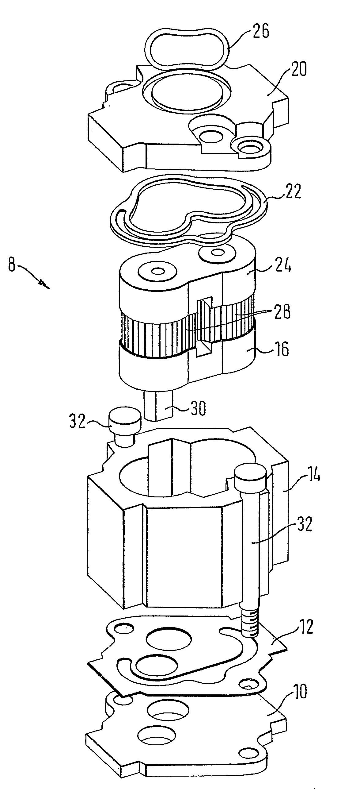
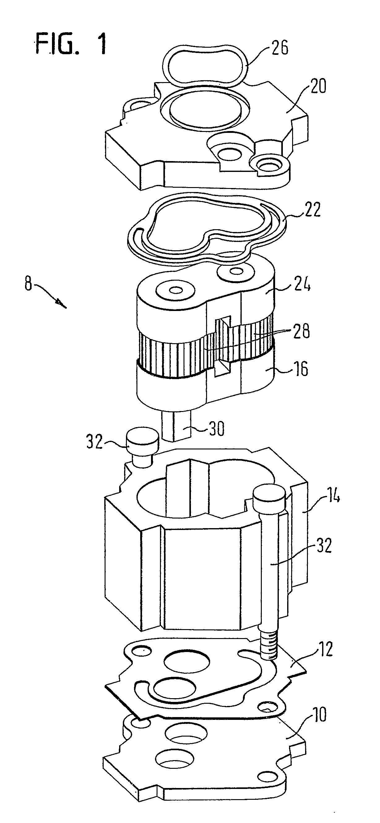
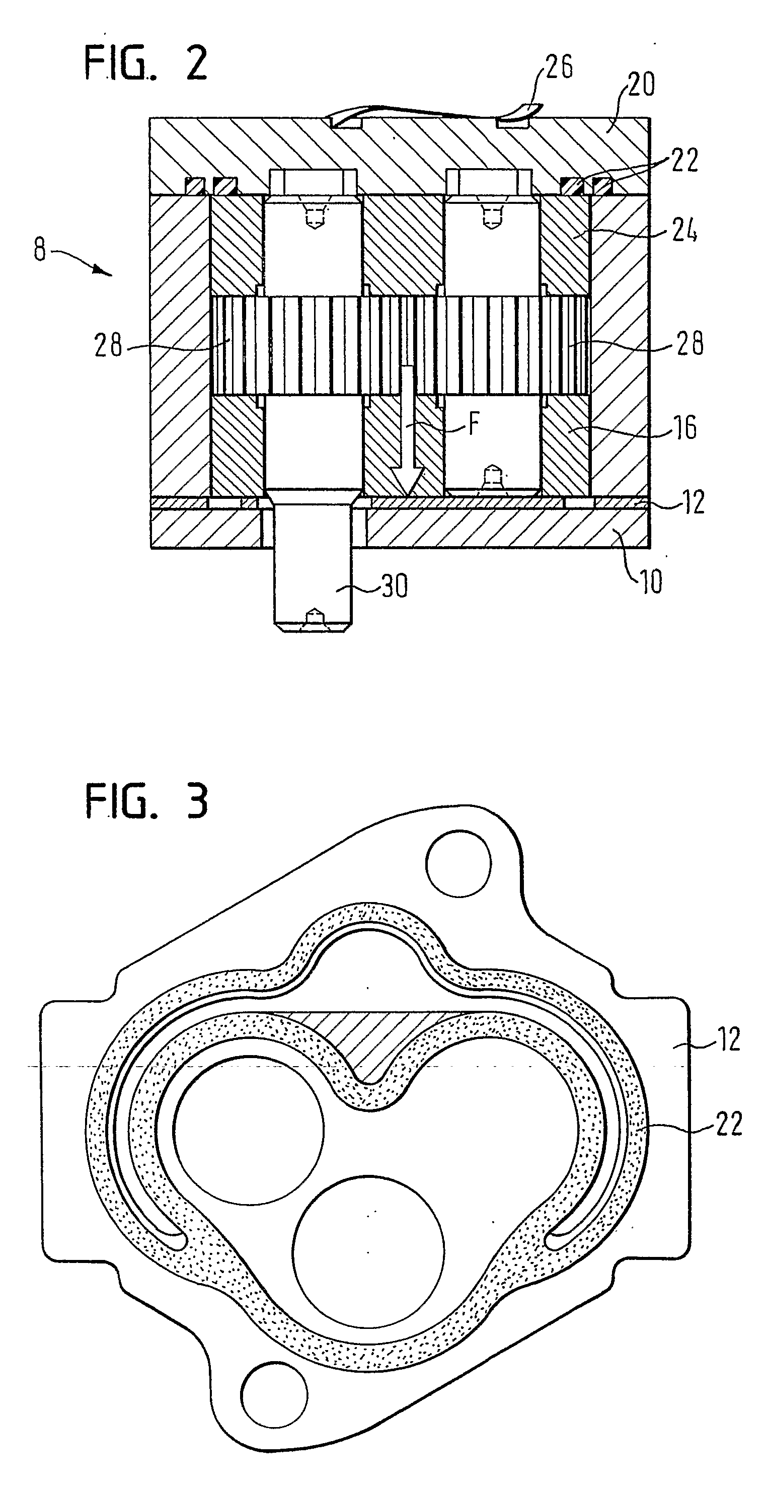
[0019]FIG. 1 illustrates a power steering system hydraulic pump 8 having two pump components which are to be sealed and a first pump cover 10, a flat sealing element being provided between the pump components which are to be sealed and the first pump cover 10. In this example, the pump components which are to be sealed are a housing 14 and a first bearing rest 16. The hydraulic pump 8 additionally comprises a second pump cover 20 having a ring seal22, the ring seal 22 being arranged between the second pump cover 20 and a pump component which is to be sealed. The components which are to be sealed here are a second bearing rest 24 and again the housing 14. A spring ring 26 which compensates for the axial play of the hydraulic pump 8 on installation into a motor / pump unit (not shown) is additionally illustrated on the upper side of the second pump cover 20. As in FIG. 1 an external-gear pump is shown, the pump gear, consisting of two meshing gear wheels 28, is situated between the bear...


PUM


Abstract

A power steering system hydraulic pump has a pump component which is to be sealed and a first pump cover. A flat sealing element is provided between the pump component which is to be sealed and the first pump cover.

Description

CROSS-REFERENCE TO RELATED APPLICATIONS[0001]This application is a National Stage of International Application No. PCT / EP2006 / 000461 filed Jan. 19, 2006, the disclosures of which are incorporated herein by reference, and which claimed priority to German Patent Application No. 10 2005 002 757.1 filed Jan. 20, 2005, the disclosures of which are incorporated herein by reference.BACKGROUND[0002]Various embodiments of a power steering system hydraulic pump are disclosed herein. In particular, the embodiments described herein relate to an improved power steering system hydraulic pump having a pump component, which is to be sealed, and a first pump cover.[0003]Such pumps are generally part of a motor / pump unit for power steering systems of motor vehicles. DE 203 02 535 U, and corresponding U.S. Patent Application Publication No. 2006 / 0051230 A1, both of which are incorporated by reference herein, shows a generic hydraulic pump for a power steering system which can be inserted as a prefabri...

Claims


Application Information

Patent Timeline
IPC IPC(8): F04C15/00
CPCF04C15/0026B62D5/06B62D5/07
Inventor JORDAN, MARTIN
Owner TRW AUTOMOTIVE GMBH
Why Eureka
Try Eureka