Method and system for using mechanical power to operate a hybrid electric vehicle

a hybrid electric vehicle and mechanical power technology, applied in hybrid vehicles, electric propulsion mountings, vehicle sub-unit features, etc., can solve problems such as torque disturbance in the driveline of the vehicl

Inactive Publication Date: 2009-05-14
FORD GLOBAL TECH LLC
View PDF15 Cites 12 Cited by
  • Summary
  • Abstract
  • Description
  • Claims
  • Application Information

AI Technical Summary

Problems solved by technology

Starting the engine when the vehicle is moving under the power of the electric

Method used


Image

  • Method and system for using mechanical power to operate a hybrid electric vehicle
  • Method and system for using mechanical power to operate a hybrid electric vehicle
  • Method and system for using mechanical power to operate a hybrid electric vehicle

Examples


Embodiment Construction

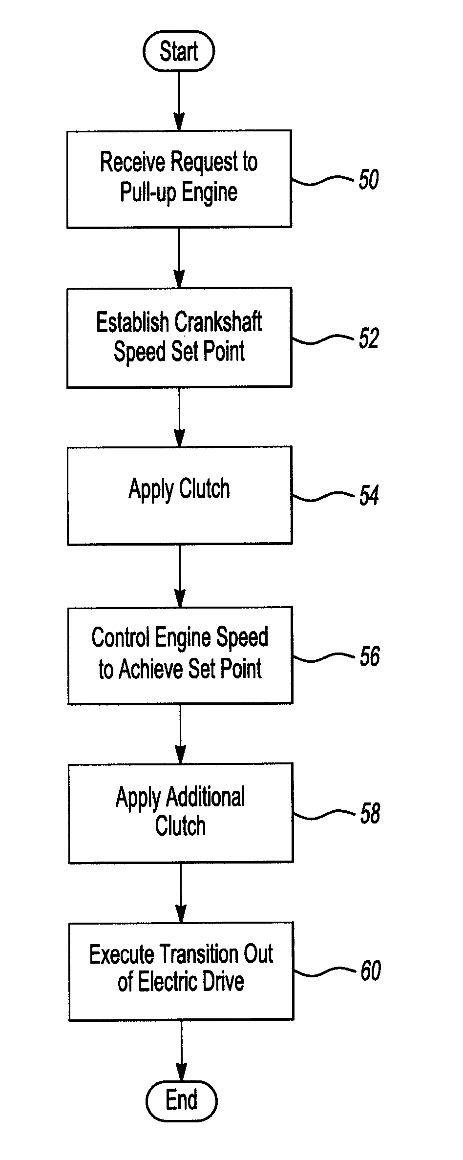
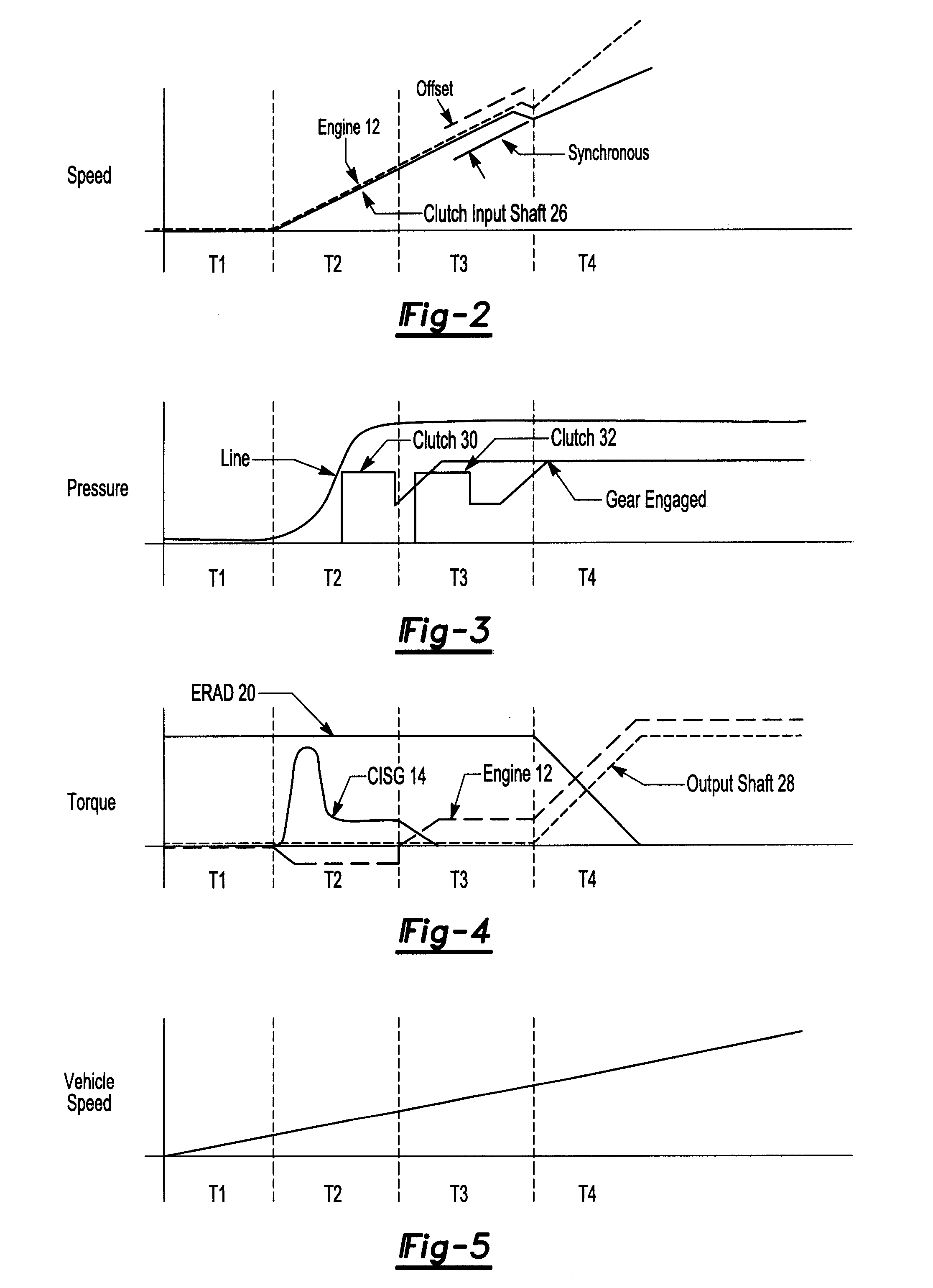
[0023]Strategies to control electric motors and transmissions of hybrid electric vehicles (HEVs) while shifting in and out of neutral are disclosed. In one example, an engine is shut down during conditions in which the engine operates inefficiently. An electric axle drive is connected to an axle, front and / or rear, and may provide torque directly to wheels. When the engine is shut down, a transmission will transition from a drive gear to a neutral gear so that spin and pump losses are not carried while driving electrically. A crankshaft of the engine will be spun up to a desired speed and the transmission will transition from the neutral gear to an appropriate gear based on a shift schedule. A target transmission input speed is commanded to be a synchronous speed plus an offset. The offset may be positive or negative. This is done to ensure a smooth transition out of electric axle drive propulsion.

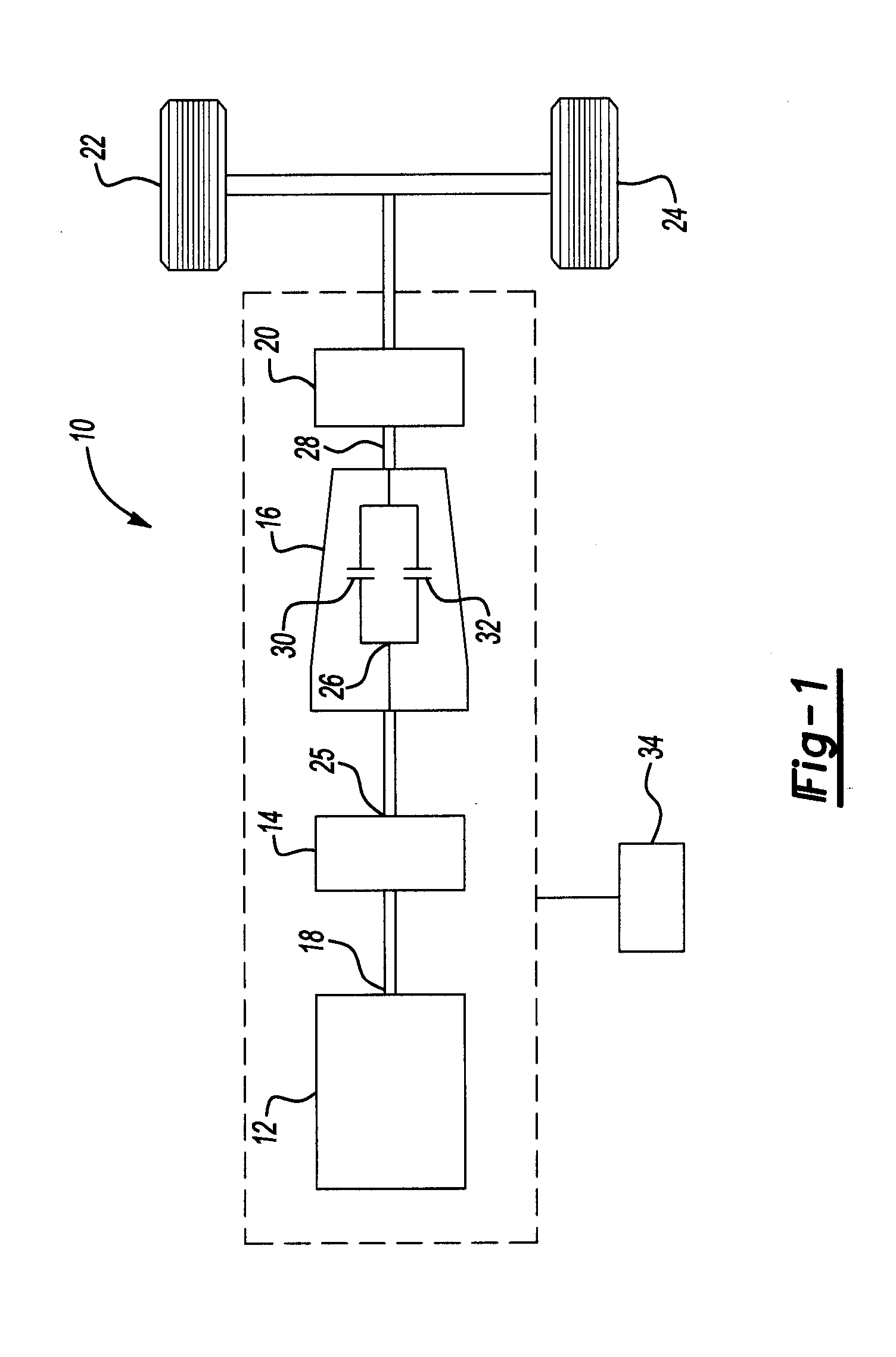
[0024]An exemplary rear wheel drive HEV system 10 of FIG. 1 includes an internal combu...


PUM


Abstract

An automotive transmission transitions from a drive gear to a neutral gear when an engine is shutdown. During a rolling pull-up, a crankshaft of the engine will be spun up to a desired speed and the transmission will transition from the neutral gear to an appropriate gear based on a shift schedule. A target transmission input speed is commanded to be a synchronous speed plus an offset to smoothly transition out of electric axle drive propulsion.

Description

BACKGROUND[0001]1. Field of the Invention[0002]The invention relates to methods and systems for using mechanical power to operate a hybrid electric vehicle.[0003]2. Background Art[0004]A hybrid electric vehicle (HEV) uses power generated by an internal combustion engine and an electric motor to move the vehicle. A HEV may provide improved fuel economy compared to conventional vehicles. One technique for improving the fuel economy in a HEV is to shutdown the engine when it is not needed to move the vehicle. In this situation, the electric motor provides power to move the vehicle. The engine then is started as needed. Starting the engine when the vehicle is moving under the power of the electric motor may cause a noticeable torque disturbance in a driveline of the vehicle.[0005]Various methods are used to control an engine start in a vehicle. U.S. Pat. No. 7,013,213 to McGee et al. is an example of such a method. According to McGee et al., a smoothness factor is calculated to determin...

Claims


Application Information

Patent Timeline
IPC IPC(8): B60W10/02B60W10/08B60L50/16
CPCB60K1/02Y10T477/26B60K6/442B60K6/485B60L2240/486B60W10/06B60W10/08B60W20/00B60W2520/10B60W2540/16B60W2710/0644B60W2710/1061B60Y2400/428Y02T10/6226Y02T10/6234Y02T10/6286Y10T477/27Y10T477/32B60K6/38Y02T10/62B60K6/48B60W10/02B60W20/10
Inventor SILVERI, ANDREW JOHNCOLVIN, DANIEL SCOTTKRASKA, MARVIN PAUL
Owner FORD GLOBAL TECH LLC
Why Eureka
Try Eureka