
Lancing unit and lancing apparatus

a technology applied in the field of lancing unit and lancing apparatus, to achieve the effect of reducing or eliminating

Inactive Publication Date: 2009-05-14
ARKRAY INC
View PDF11 Cites 12 Cited by
  • Summary
  • Abstract
  • Description
  • Claims
  • Application Information

AI Technical Summary

Benefits of technology

The solution reduces the size of the lancing apparatus, ensures proper needle sterility and airtightness, enhances blood collection efficiency, and lowers manufacturing costs by simplifying the structure and reducing the number of parts.

Problems solved by technology

However, it is troublesome to often go to a medical institution for measuring the blood glucose level.
First, in the prior art arrangement, to mount the lancet 90 and the test piece 92 to the lancing apparatus 8, both of the first and the second housings 91A and 91B of the lancing unit 9 need be mounted to the lancing apparatus 8. Therefore, the front end of the lancing apparatus 8 needs to be made relatively large. As a result, the size of the lancing apparatus 8 increases, which is inconvenient for carrying.
Secondly, from a hygienic point of view, the needle 90a of the lancet 90 need be hermetically sealed in the first housing 91A of the lancing unit 9. For this purpose, the portion where the first housing 91A and the lancet 90 are fitted together need be hermetically sealed. On the other hand, after the first housing 91A along with the lancet 90 is mounted to the lancing apparatus 8 and the lancet holder 81 is advanced, the lancet 90 needs to move smoothly relative to the first housing 91A in accordance with the movement of the lancet holder. However, to hold the lancet 90 in the first housing 91A in such a manner as to satisfy the above two requirements is not easy. Thus, the needle 90a of the lancet 90 sometimes is not hermetically sealed, or the lancet 90 after it is mounted to the lancing apparatus 8 sometimes does not move smoothly.
Thirdly, in the lancing apparatus 8, it is desirable that the blood introduction portion 95 is located as close to the lancing position as possible. This is because, as the blood introduction portion 95 is farther from the lancing position, the blood is less likely to come into contact with the blood introduction portion 95 properly. Even when the blood comes into contact with the blood introduction portion 95, the amount of blood reaching the test piece 92 is small, whereby accurate analysis result may not be obtained. Since the first case 91A is fixed to the housing 80 while the lancet 90 moves reciprocally along a predetermined path, the distance s between the path and the blood introduction portion 95 is always constant. In the prior art arrangement, therefore, to locate the blood introduction portion 95 close to the lancing position, the blood introduction portion 95 need be provided close to the needle 90a of the lancet 90 in the state of the lancing unit 9 shown in FIG. 26A (though this figure does not show the blood introduction portion). However, in actually designing and manufacturing the lancing unit 9, various points need be taken into consideration such as reduction in size of the entire unit and the airtightness of the first case 91A, so that it is sometimes difficult to locate the blood introduction portion 95 sufficiently close to the needle 90a of the lancet 90. Therefore, in the prior art arrangement, it is difficult to locate the blood introduction portion 95 sufficiently close to the lancing position, so that the amount of blood introduced to the test piece 92 is sometimes insufficient.
Fourthly, since the lancing unit 9 requires the cover 93 in addition to the first and the second housings 91A and 91B, the number of parts of the lancing unit 9 is large, whereby the manufacturing cost is relatively high.

Method used


Image

  • Lancing unit and lancing apparatus
  • Lancing unit and lancing apparatus
  • Lancing unit and lancing apparatus

Examples


Embodiment Construction

[0069]Preferred embodiments of the present invention will be described below in detail with reference to the accompanying drawings.

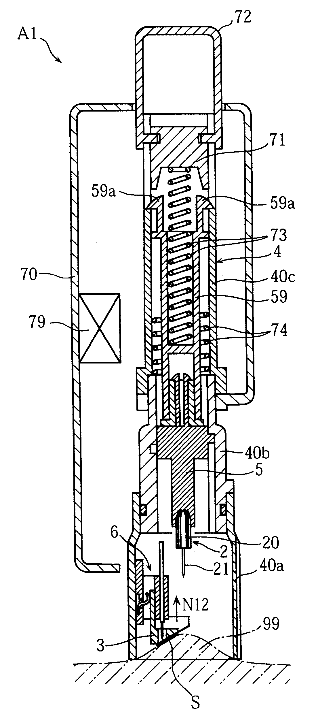
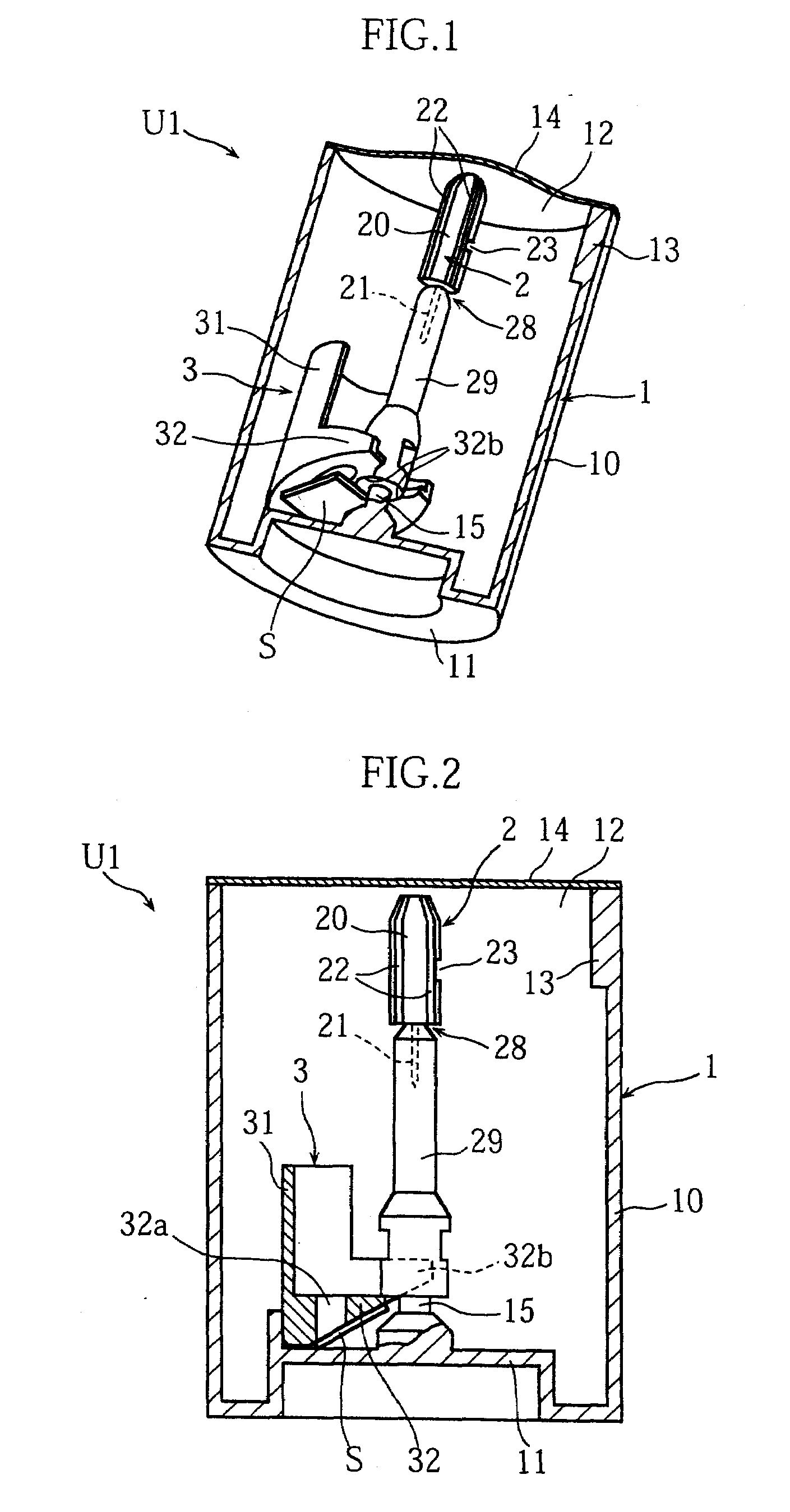
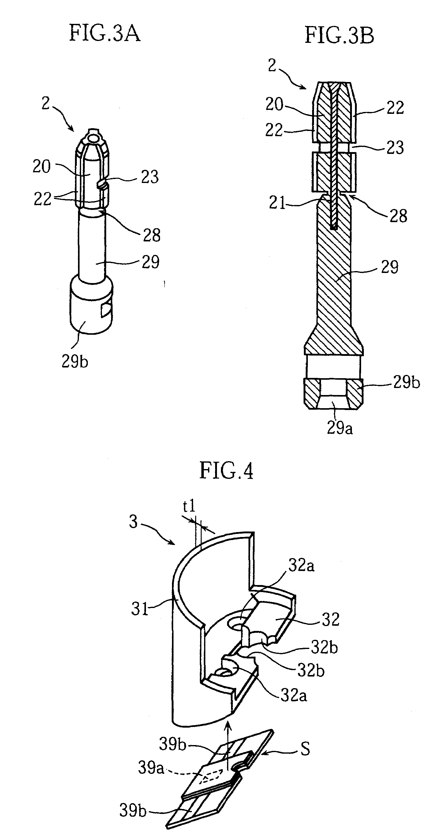
[0070]FIGS. 1-6 show an example of lancing unit and the structural parts according to the present invention. As better shown in FIGS. 1 and 2, the lancing unit U1 in this embodiment includes a case 1, a lancet 2, a cap 29 and a sensor holder 3.

[0071]The case 1 is an example of supporter according to the present invention. The case 1, which is made of synthetic resin, includes a generally cylindrical tubular portion 10 having an end (upper end) formed with an opening 12, and a bottom portion 11 connected to another end (lower end) of the tubular portion 10. The tubular portion 10 has an inner circumferential surface formed with a projection 13, which serves as a rotation stopper in fitting the case 1 around a part of a lancing apparatus A1, which will be described later. A film 14 as a lid for closing the opening 12 is bonded to the upper surface of the c...


PUM


Abstract

A lancing unit (U1) includes a lancing member (2), an auxiliary part (3) which is separate from the lancing member (2), and a supporter (1) detachably supporting these. Preferably, the lancing unit (U1) further includes a cap (29) which covers a needle (21) of the lancing member (2) and which is detachable from the lancing member (2), and the lancing member (2) is supported by the supporter (1) via the cap (29).

Description

CROSS REFERENCE TO RELATED APPLICATIONS[0001]This application is a Continuation of U.S. Ser. No. 10 / 519,892, filed Dec. 29, 2004, which is a National Stage of PCT / JP2003 / 008383 filed Jul. 1, 2003, each of which are incorporated herein by reference.TECHNICAL FIELD[0002]The present invention relates to a lancing apparatus used to extract body fluid such as blood. It also relates to a lancing unit holding a disposable part as a unit and used as mounted to such a lancing apparatus.BACKGROUND ART[0003]For diabetes treatment, management of the blood glucose level by a patient himself or herself is important for maintaining the blood glucose level in a normal range. Particularly, for a patient of insulin-dependent diabetes, regular measurement of the blood glucose level is essential to maintain the blood glucose level in a normal range. However, it is troublesome to often go to a medical institution for measuring the blood glucose level. Conventionally, therefore, apparatuses which enable ...

Claims


Application Information

Patent Timeline
Patent Type & Authority Applications(United States)
IPC IPC(8): A61B5/151A61B17/32A61B5/15
CPCA61B5/1411A61B5/150022A61B5/150099A61B5/150358A61B5/150412A61B5/150519A61B5/150549A61B5/150564A61B5/150618A61B5/150717A61B5/150725A61B5/15113A61B5/15117A61B5/1519A61B5/15194A61B5/157A61B5/150557
Inventor SAKATA, TETSUYAMATSUMOTO, DAISUKE
Owner ARKRAY INC
Learn More