
Image sensor module with substrate and frame and method of making the same

a technology of image sensor module and substrate, which is applied in the field of image sensor module with substrate and frame and the same making method, can solve the problems of troublesome mounting of image sensor module b>100/b> through such two steps, increase in manufacturing cost, and burden on the manufacturer, etc., and achieve the effect of reducing or eliminating

Inactive Publication Date: 2007-01-23
ROHM CO LTD
View PDF14 Cites 34 Cited by
  • Summary
  • Abstract
  • Description
  • Claims
  • Application Information

AI Technical Summary

Benefits of technology

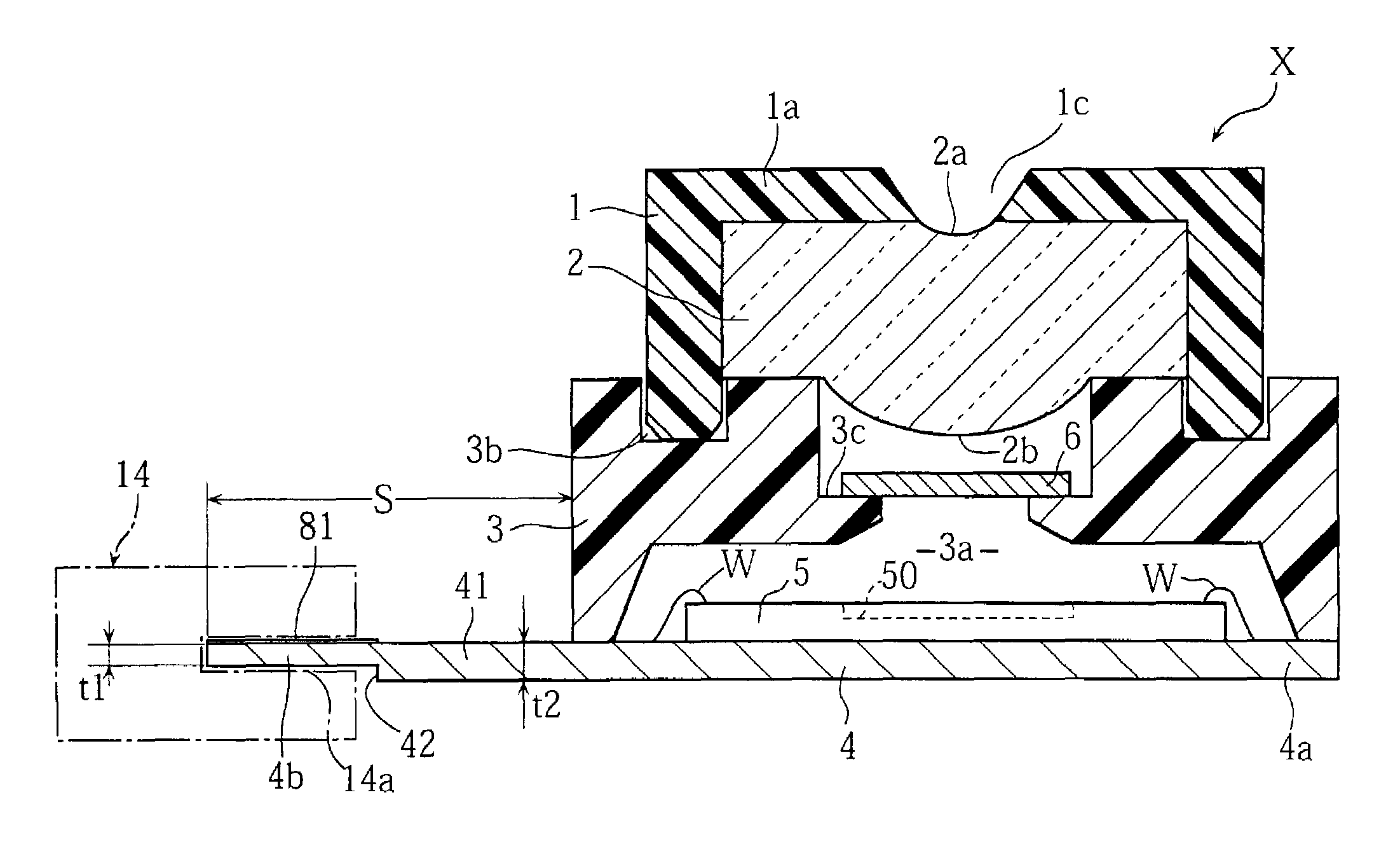
The present invention provides an image sensor module that solves problems associated with conventional image sensor modules. The image sensor module comprises a substrate on which an image sensor chip is mounted, and a frame mounted to the substrate to surround the image sensor chip. The substrate includes a projecting portion with a plurality of terminals electrically connected to the image sensor chip. The plurality of terminals are aligned along an edge of the projecting portion at a predetermined pitch. The end of the projecting portion is smaller in thickness than other portions of the substrate. The image sensor module also includes an optical filter for blocking light of a predetermined wavelength range and an image forming lens. The method of making the image sensor module involves mounting a plurality of image sensor chips on an aggregate board, mounting a plurality of frames on the aggregate board so that each frame surrounds a respective one of the image sensor chips, and dividing the aggregate board into a plurality of substrates so that each frame and the relevant set of terminals are located on a same substrate.

Problems solved by technology

However, the mounting of the image sensor module 100 through such two steps is troublesome.
Thus, the maker has to substantially perform assembling of the image sensor module, which is great burden on the manufacturer.
Therefore, the number of parts and the number of process steps for making an image sensor module are increased, which leads to an increase in the manufacturing cost.

Method used


Image

  • Image sensor module with substrate and frame and method of making the same
  • Image sensor module with substrate and frame and method of making the same
  • Image sensor module with substrate and frame and method of making the same

Examples


Embodiment Construction

[0025]Preferred embodiments of the present invention will be described below in detail with reference to the accompanying drawings.

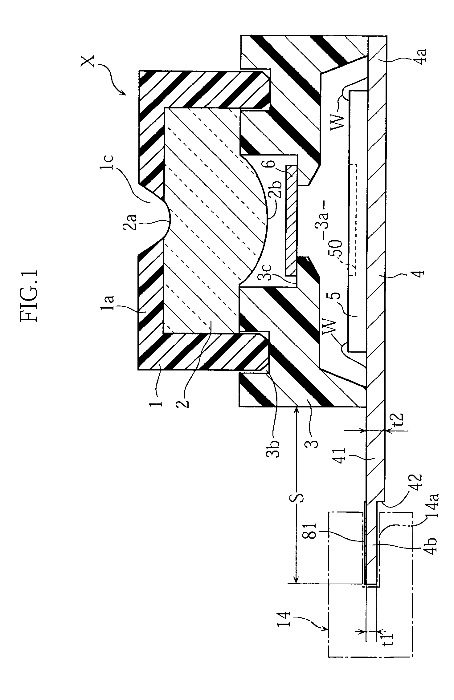
[0026]FIG. 1 illustrates an example of image sensor module according to the present invention. The image sensor module X in this embodiment comprises a substrate 4, an image sensor chip 5, a frame 3, and a lens holder 1 holding a lens 2.

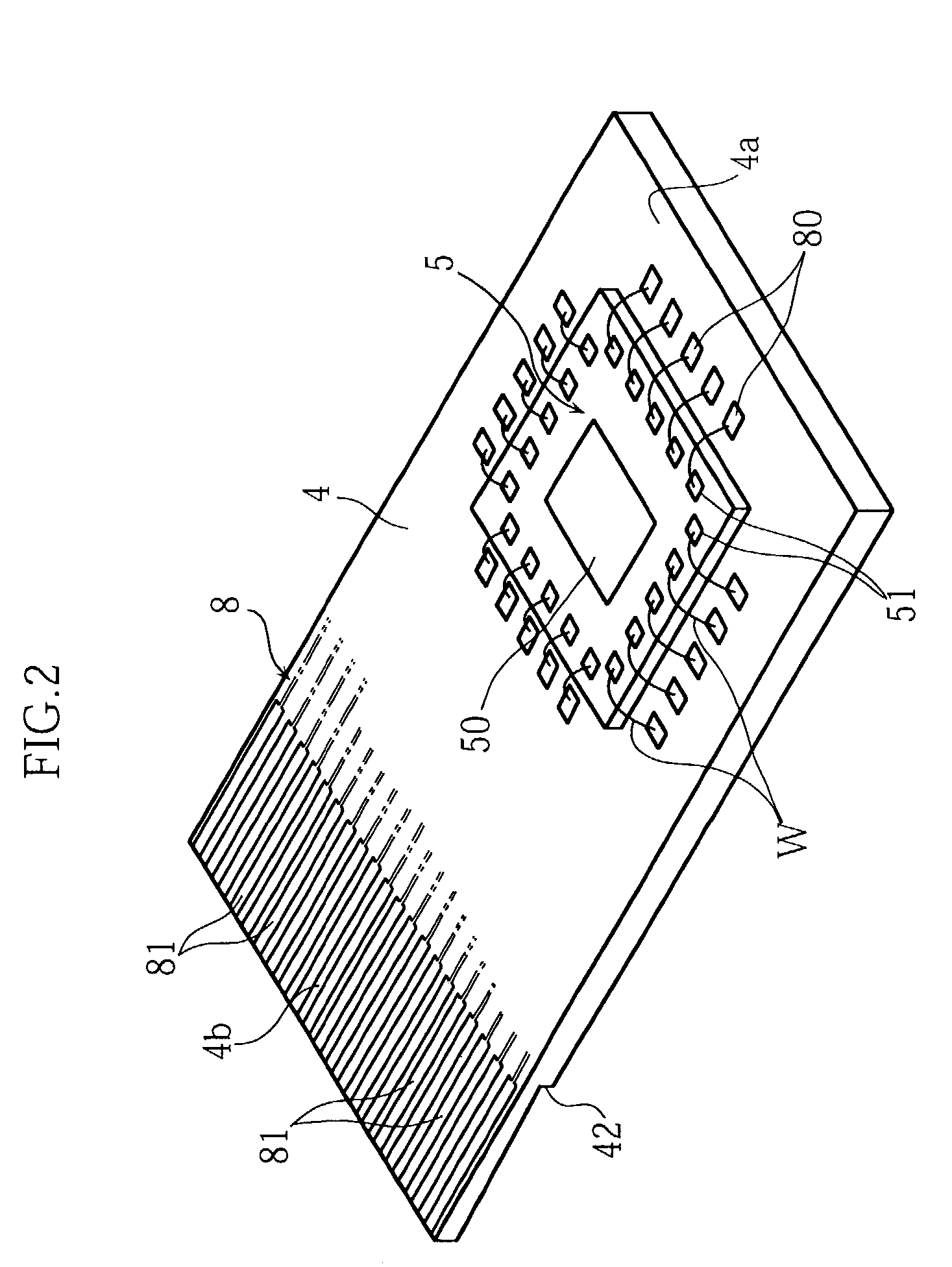
[0027]The substrate 4, which may be made of glass-fiber-reinforced epoxy resin for example, has an elongated rectangular configuration. The substrate 4 has an obverse surface (upper surface) on which the image sensor chip 5 is mounted at a location offset from the middle portion of the substrate 4 toward one end 4a in the longitudinal direction. As shown in FIG. 2, the image sensor chip 5, which may be a CCD or MOS solid-state image pickup device for example, has an upper surface provided with a light receiving portion 50 and a plurality of electrodes 51. The light receiving portion 50 includes a plurality of non-illustra...


PUM


Abstract

An image sensor module (S) includes a substrate (4) having a projecting portion (41) projecting sideways from a frame (3). The projecting portion (41) has an end (4b) provided with a plurality of terminals (81) electrically connected to an image sensor chip (5). The image sensor module (X) can be easily connected to another apparatus by inserting the end (4b) of the projecting portion (41) into a socket type connector.

Description

BACKGROUND OF THE INVENTION[0001]1. Field of the Invention[0002]The present invention relates to an image sensor module for use as a structural part of a digital camera or a camera-equipped cell phone and also relates to a method of making the same.[0003]2. Description of the Related Art[0004]FIG. 5 illustrates an example of prior art image sensor module. The illustrated image sensor module 100 comprises a substrate 104 having an obverse surface on which an image sensor chip 105 is mounted and a frame 103 is attached. A lens holder 101 holding a lens 102 is mounted to the frame 103. With this structure, light traveling from an object passes through the lens 102 to form an image of the object on the image sensor chip 105. The substrate 104 has a reverse surface provided with a plurality of terminals 106 electrically connected to the image sensor chip 105. The image sensor module 100 is mounted on a mother board 107 in a cell phone for constituting the camera-equipped cell phone, for ...

Claims


Application Information

Patent Timeline
Patent Type & Authority Patents(United States)
IPC IPC(8): H01L23/02G02B7/02H01L27/14H01L27/146H04N25/00
CPCH01L27/14618H01L27/14625H04N5/2253H04N5/2254H01L2224/48091H01L2924/3025H01L2924/00014H01L2924/00H04N23/55H04N23/54
Inventor ONISHI, HIROAKIFUJIMOTO, HISAYOSHI
Owner ROHM CO LTD
Learn More