
Blower duct

a technology of blower ducts and ducts, which is applied in the direction of machines/engines, liquid fuel engines, and turbine growth, etc., can solve the problems of air pressure loss generation and deterioration of the blower air blowing efficiency, so as to prevent pressure loss and reduce pressure loss

Inactive Publication Date: 2009-05-21
HUSQVARNA ZENOAH
View PDF38 Cites 13 Cited by
  • Summary
  • Abstract
  • Description
  • Claims
  • Application Information

AI Technical Summary

Benefits of technology

[0006]It is a principal object of the invention to provide a blower duct helping to achieve an improvement in air blowing efficiency.
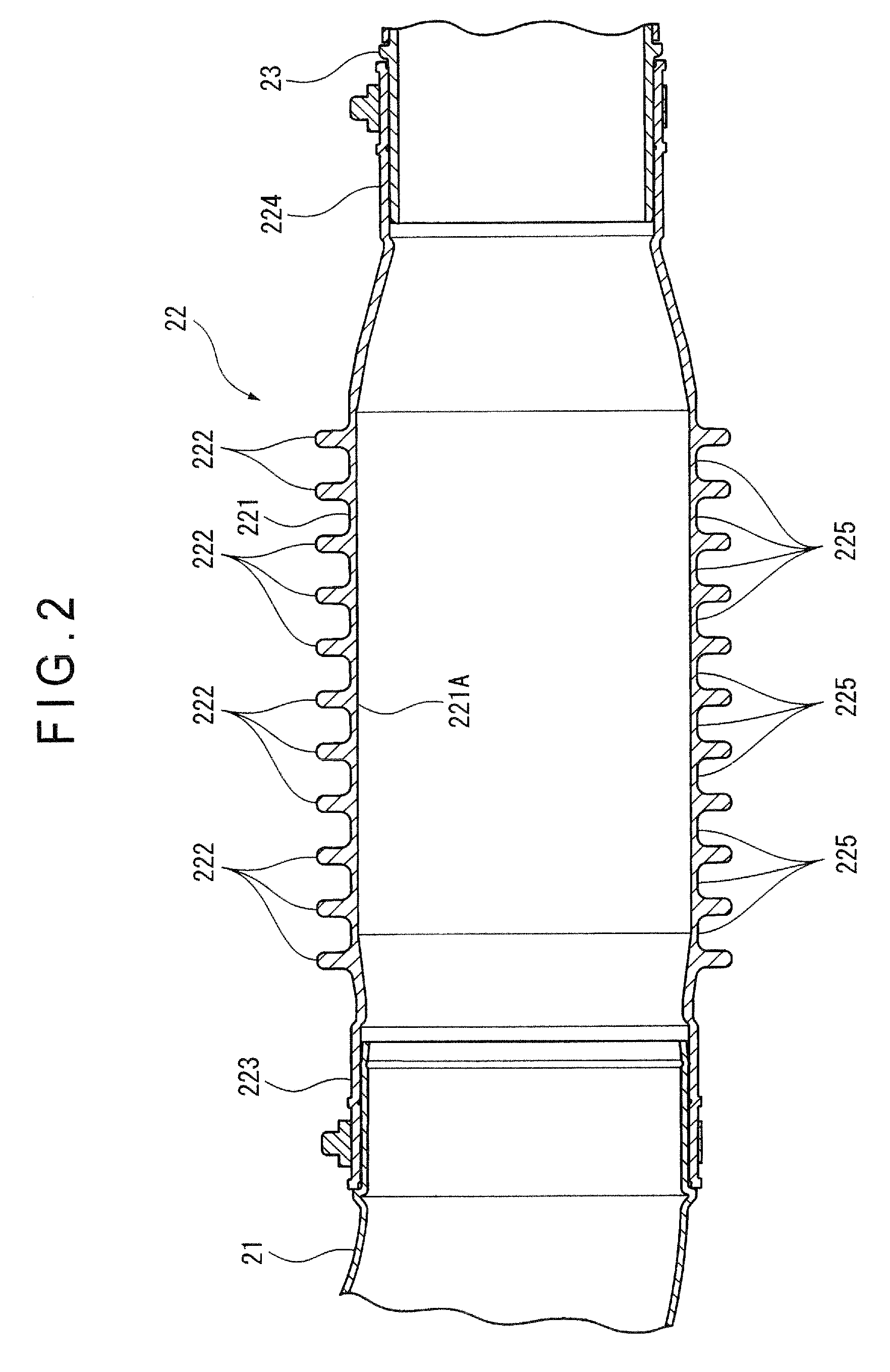
[0008]According to the aspect of the invention, when the flexible tube is not greatly contracted, that is, when it is in a normal state in which no external force is being applied thereto, or when, even if an external force is applied thereto, it is expanded due to that external force, the inner peripheral surface of the flexible tube is a smooth surface, so no turbulence is generated in the air passing through the tube, and pressure loss is prevented. In a state in which the tube is curved, contraction occurs on the inner side of the curved portion of the tube, and the inner peripheral surface of the contracted portion exhibits protrusions and recesses. However, on the outer side of the curved portion, the tube is expanded, and the inner peripheral surface of this expanded portion reliably provides a smooth surface, so it is possible to reduce the pressure loss.

Problems solved by technology

When there are protrusions and recesses on the inner surface of the bendable portion, turbulence is generated in the airflow from the blower, resulting in generation of air pressure loss.
Thus, as a result of the pressure loss due to this air turbulence, the wind pressure becomes so much the lower, resulting in a deterioration in air blowing efficiency of the blower.

Method used


Image

  • Blower duct
  • Blower duct
  • Blower duct

Examples


Embodiment Construction

)

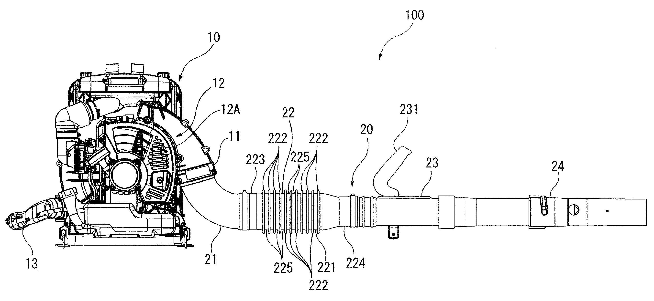
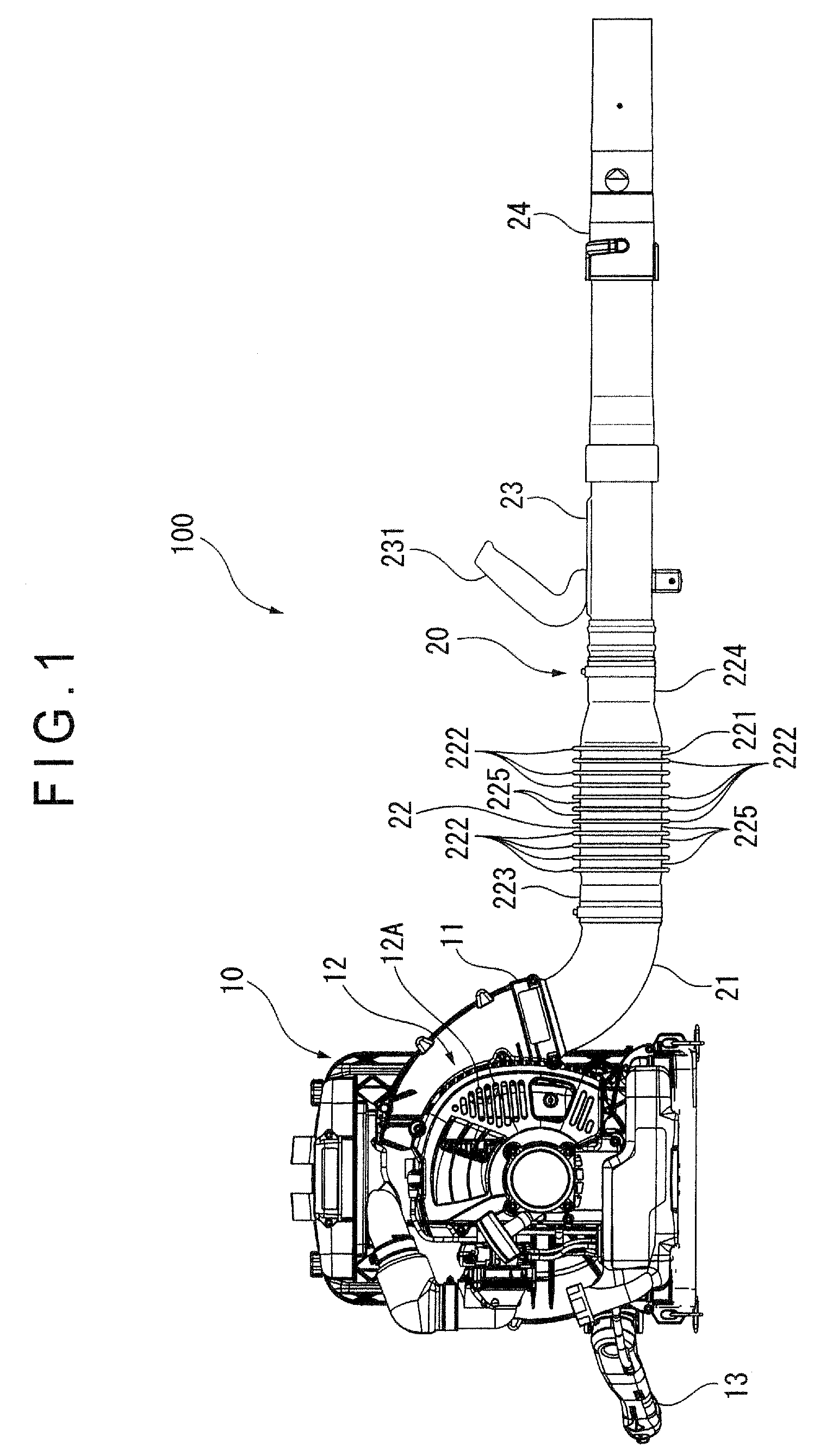
[0011]In the following, an exemplary embodiment of the invention will be described with reference to the drawings. FIG. 1 is a general plan view of a blower according to the exemplary embodiment. FIG. 2 is a sectional view of a part of the duct of the exemplary embodiment taken along the axis thereof.

[Construction of the Portable Blower]

[0012]In FIG. 1, numeral 100 indicates a portable blower. The portable blower 100 is formed in a size and weight allowing the operator to carry it on operator's back, with operator's hand, etc. The portable blower 100 is equipped with a blower main body 10 and a duct 20 connected to the blower main body 10. Air sucked in by the blower main body 10 is supplied to the duct 20, and with the air blown out of the duct 20, it is possible to blow away dust, fallen leaves, etc.

[0013]The blower main body 10 is equipped with an air sending port 11 to which the duct 20 is connected, a volute 12 supplying air to the air sending port 11, and a throttle 13 for ad...


PUM


Abstract

A portable-blower duct has a bendable portion whose inner peripheral surface is a cylindrical surface without any protrusions or recesses in a normal state or in an expanded state, that is, unless it is greatly curved. With this construction, no turbulence is generated in air passing through a tube, thereby making it possible to suppress pressure loss. Thus, the flow velocity of air guided through the duct is not reduced, thereby suppressing a deterioration in air blowing efficiency. Even when the tube is curved, the outer side of the curved portion is expanded, and the corresponding portion of the inner peripheral surface remains a smooth surface, thus making it possible to minimize the air pressure loss.

Description

CROSS-REFERENCE TO RELATED APPLICATION[0001]The present application is a Divisional Application of U.S. application Ser. No. 11 / 584,023 filed Oct. 20, 2006 which is incorporated herein by reference.1. FIELD OF THE INVENTION[0002]The present invention relates to a blower duct, in particular a duct equipped with a bendable portion capable of changing a direction of air discharged from a blower.2. DESCRIPTION OF RELATED ART[0003]Hitherto, there has been known a portable blower which performs cleaning by blowing away dust, fallen leaves, etc, with air sucked therein (see, for example, JP 2003-97493 A, FIGS. 1 through 3).[0004]The blower disclosed in the above-mentioned publication is equipped with a blower main body and a duct mounted to a forward end portion of the blower main body. The duct is equipped with a bendable portion connected to the blower, a rotary portion connected to the bendable portion, a muffler connected to the rotary portion and a nozzle connected to the muffler. The...

Claims


Application Information

Patent Timeline
Patent Type & Authority Applications(United States)
IPC IPC(8): A47L5/14F04D29/44
CPCF16L11/15A01G20/00A01G20/47
Inventor NAKAZAWA, SATOSHIYAMAZAKI, MAKISAITO, TAKESHI
Owner HUSQVARNA ZENOAH
Learn More