Connector

a technology of connecting rods and connecting rods, applied in the direction of pipe connection arrangements, roof coverings, branching pipes, etc., can solve the problems of system inoperable, unsatisfactory results, and potential to destroy animal and plant li

Inactive Publication Date: 2009-05-21
ROLLING STONE CLEANING
View PDF2 Cites 5 Cited by
  • Summary
  • Abstract
  • Description
  • Claims
  • Application Information

AI Technical Summary

Benefits of technology

[0015]a by-pass portion which is moveable between a non by-pass configuration and a by-pass configuration wherein when the by-pass portion is in the non by-pass configuration this allows liquid to pass through the inlet and exit the outlet;characterised in that the connector is configured so that when the by-pass portion is in the by-pass configuration there is a region of the internal surface of the connector which at least partially overlaps the by-pass portion so that liquid entering the inlet can be redirected along the by-pass portion and out the by-pass outlet to effectively prevent liquid from exiting the outlet.
[0028]In use, the flap may be moved into a non by-pass configuration in order to achieve free communication between the inlet and the outlet. Thus, in the non by-pass configuration the connector allows a down-pipe to function in a normal manner.
[0032]In use, the flap may also move into a by-pass configuration, to prevent communication between the inlet and the outlet.
[0048]the formation of an effective by-pass which prevents water and debris from passing through the outlet;
[0049]the by-pass portion constructed from a single piece of material, without any obstructing or supporting rib(s) thus preventing debris from being trapped inside the down-pipe connector;
[0050]less risk of the down-pipe connector being inoperable through mechanical failure as there are few movable parts or catches;

Problems solved by technology

These chemicals have the potential to destroy animal and plant life so this is not a satisfactory outcome.
However, this system has numerous disadvantages.
Therefore if one of the parts is broken, rusted or unable to be used then the system is inoperable.
There is also potential for some debris to get caught in between the plates, preventing efficient operation of the system.
However this system also incorporates many moveable parts that are prone to rust or breakage that may leave the system unusable.
Further, the diverter plate does not form a liquid tight seal, therefore the possibility of toxic chemicals, used to clean the roof or spouting, still being able to flow down the outlet into the drainage system exists.
This has the potential to cause problems, particularly if the catch is broken or rusted and therefore can not be used.
Thus, if toxic cleaning solutions are being used to clean the gutters or the roof, there is a chance chemicals could leak between the by-pass plate and down into the drainage system.
The Marley diverter however, does not create a seal or otherwise effectively block the main outlet of the down-pipe.
Another disadvantage with the Marley system is that there is also an internal reinforced section that is located in the centre of the by-pass portion.
When debris is being flushed down the down-pipe, there is an opportunity for the debris to get caught up and block the down-pipe.

Method used


Image

  • Connector
  • Connector
  • Connector

Examples


Embodiment Construction

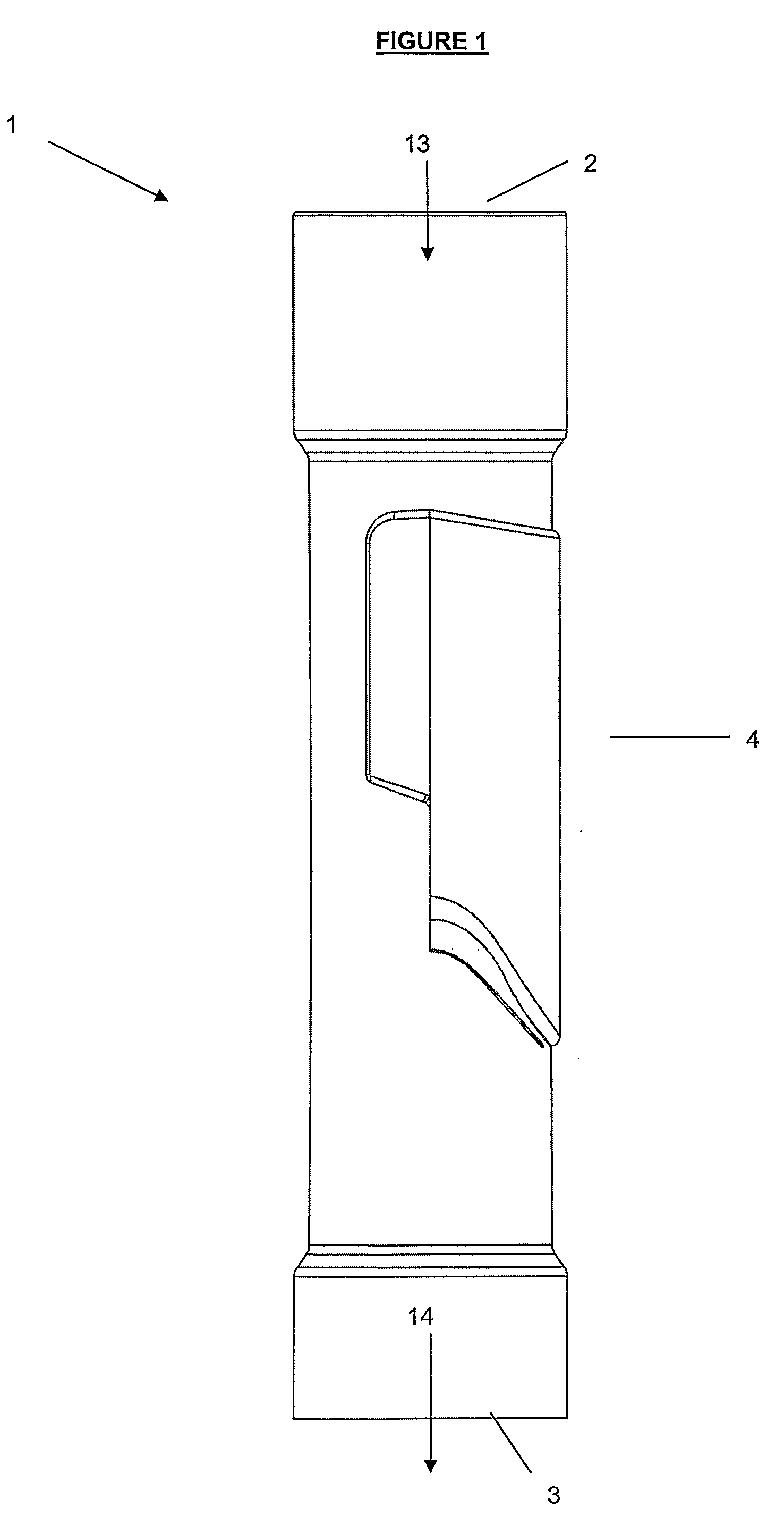
[0060]With respect to FIG. 1, there is a connector in the form of a down-pipe connector generally indicated by arrow 1 in a non by-pass configuration. The down-pipe connector 1 is substantially tubular in nature.

[0061]The down-pipe connector 1 has an inlet 2 and an outlet 3. The connector 1 has a by-pass portion in the form of a flap 4, which lies substantially parallel with the side of the down-pipe connector 1.

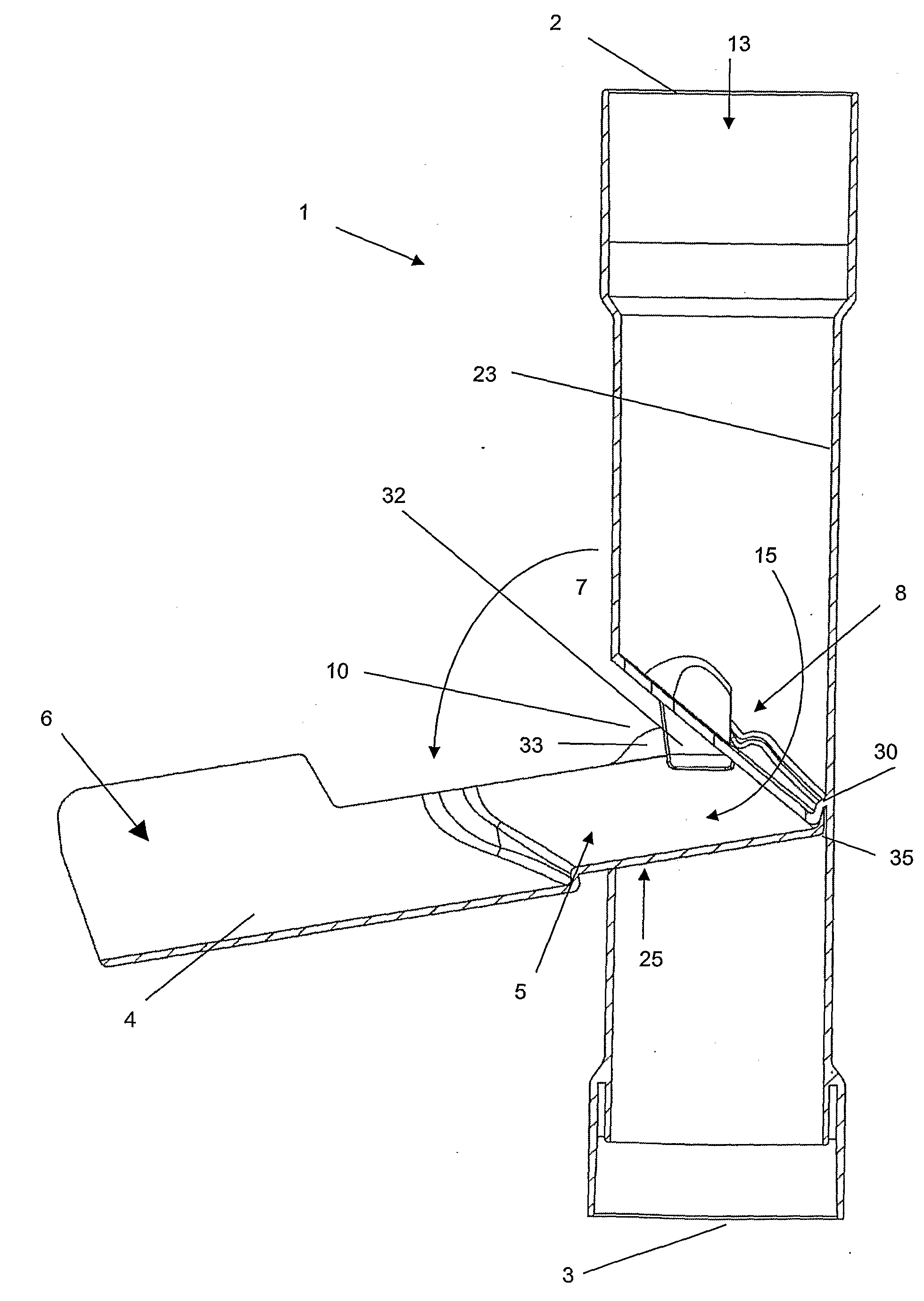
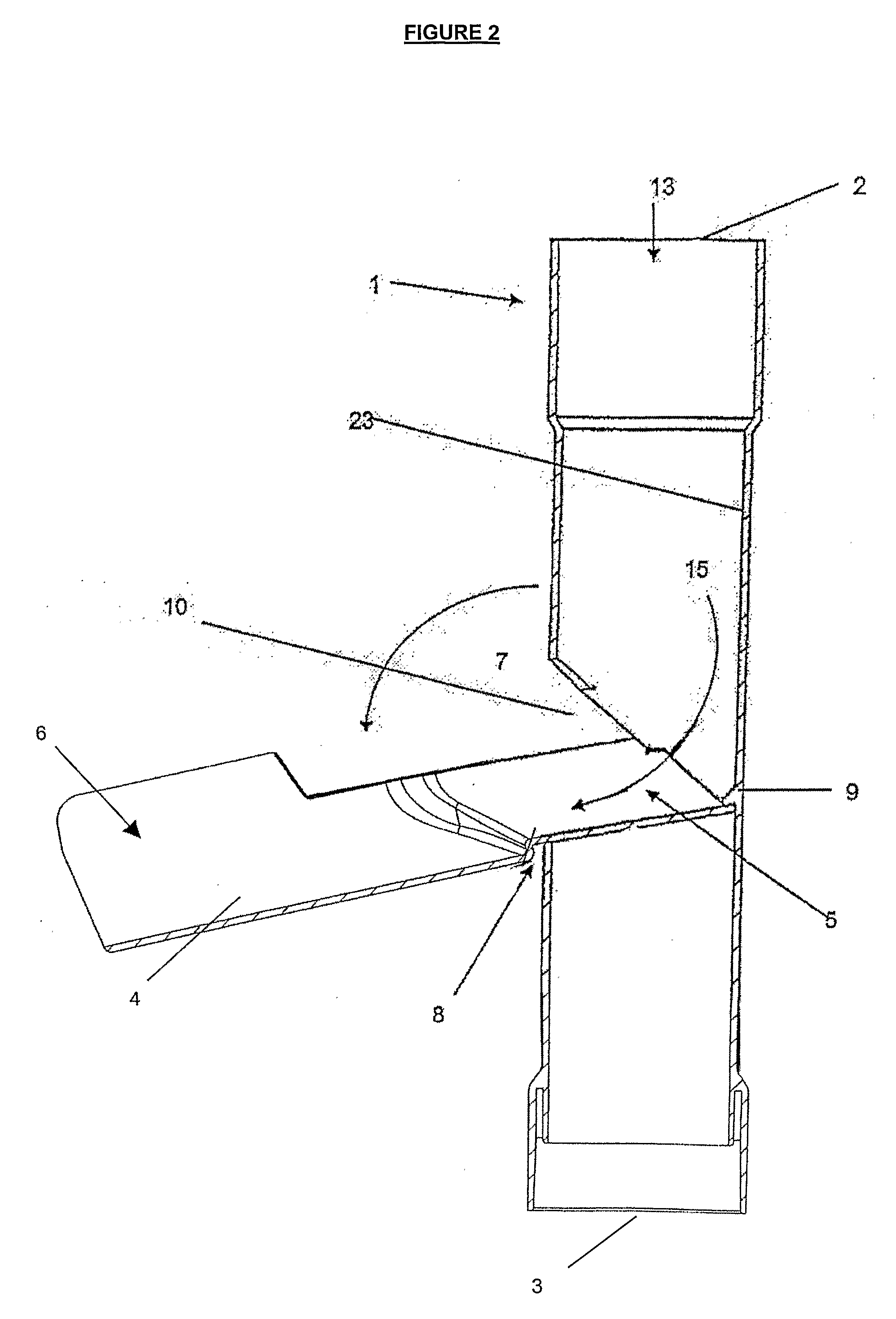
[0062]With respect to FIG. 2, there is a down-pipe connector 1 in by-pass configuration. The flap 4 has an internal portion 5 and external portion 6.

[0063]In this embodiment, the flap 4 has been moved via pivoting in the direction indicated by arrow 7 and pivots about a pivot point generally indicated by arrow 8. This causes the internal portion 5 to abut with a region of overlap in the form of a protruding lip 9 on the internal surface 23 of the connector 1. Moving the flap 4 exposes the by-pass outlet 10 on side of the down-pipe connector 1.

[0064]When the down-pipe connect...


PUM

PropertyMeasurementUnit
internal diametersaaaaaaaaaa
areaaaaaaaaaaa
frictionaaaaaaaaaa

Abstract

A connector which has an inlet and an outlet, along with an additional by-pass portion. The by-pass portion is moveable between two configurations; a non by-pass configuration and a by-pass configuration, wherein when the by-pass portion is in the non by-pass configuration this allows liquid to pass through the inlet and exit the outlet; and when the by-pass portion is in the by-pass configuration there is a region of the internal surface of the connector which at least partially overlaps the by-pass portion so that liquid entering the inlet can be redirected along the by-pass portion and out the by-pass outlet to effectively prevent liquid from exiting the outlet.

Description

TECHNICAL FIELD[0001]This invention relates to a connector. In particular, although this should not be seen as limiting, a by-pass connector that redirects liquid and / or suspended matter through an independent outlet.BACKGROUND ART[0002]The present invention may have a variety of different applications. In general however, it is envisaged the invention will be used in relation to a number of liquid collection or waste systems, although this should not be seen as limiting. For ease of reference, the present invention will now be discussed in relation to a down-pipe in a guttering system.[0003]Many people use toxic chemicals to clean out their guttering systems or to clean the roof of their house. Many of these chemicals or residues from these chemicals may be washed into the gutter system and then end up in the drainage system via the down-pipe. These chemicals have the potential to destroy animal and plant life so this is not a satisfactory outcome.[0004]At present whilst there are ...

Claims


Application Information

Patent Timeline
Patent Type & Authority Applications(United States)
IPC IPC(8): E04D13/08
CPCE04D13/08E04D2013/082F16L47/26F16L41/004E04D2013/0866
Inventor LUCAS, CHRISTOPHER FRANCIS
Owner ROLLING STONE CLEANING
Why Eureka
Try Eureka