

Torque measuring method and apparatus for motor-operated valve
- Summary
- Abstract
- Description
- Claims
- Application Information
AI Technical Summary
Benefits of technology
Problems solved by technology
Method used
Image

Examples
first embodiment
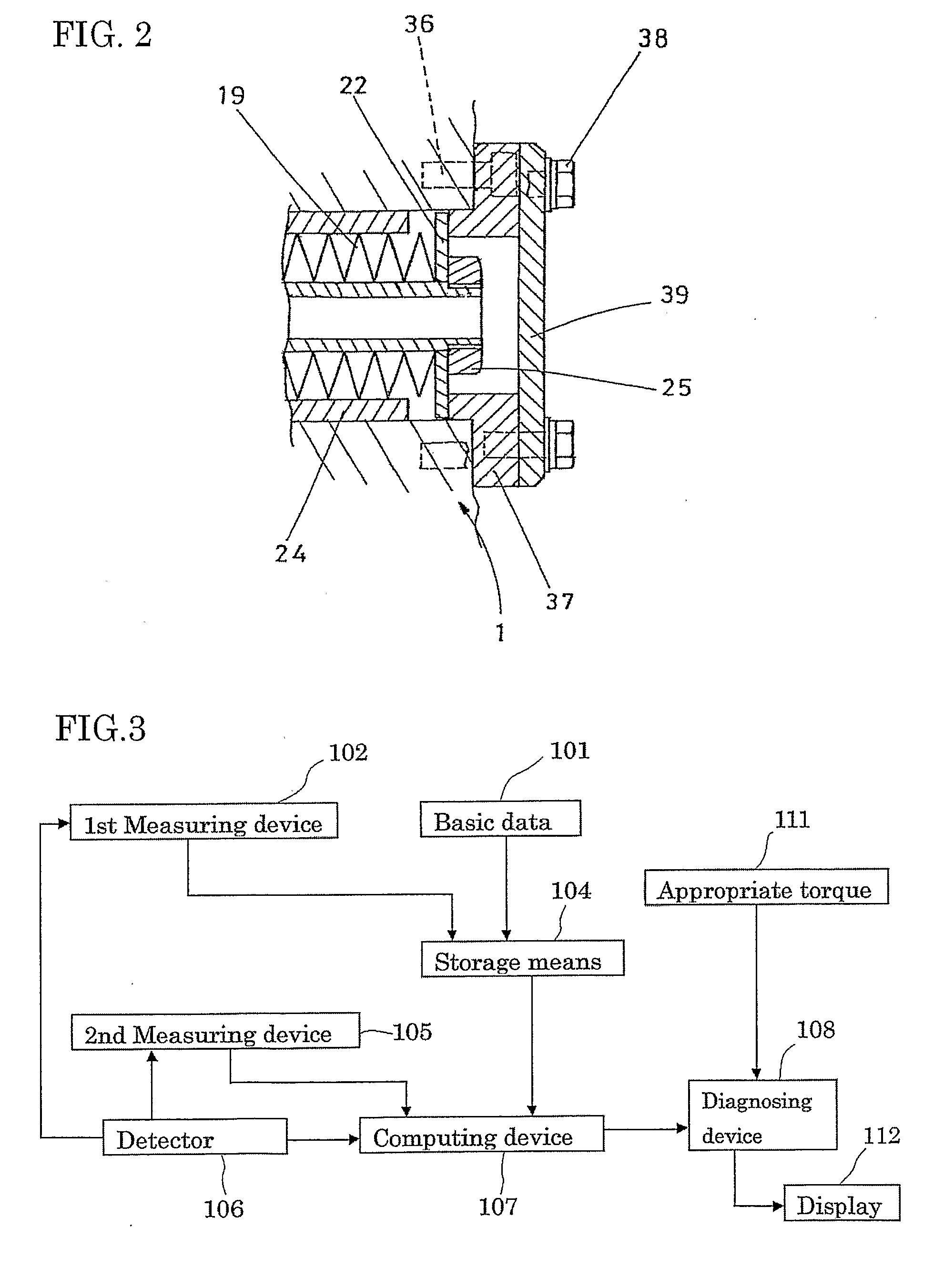
[0128]FIG. 3 is a functional block diagram of the torque measuring method and apparatus according to the first embodiment of the present invention. The torque measuring apparatus has a basic data acquisition device 101, a first, distance measuring device 102, a storage means 104, a second, distance measuring device 105, a valve operating direction detector 106, a computing device 107, a diagnosing device 108, an appropriate torque storage means 111, and a display device 112.
[0129]The basic data acquisition device 101 acquires the basic data (see Table 1). More specifically, the basic data acquisition device 101 obtains the reference amounts of compression La1 to Lan and the reference compression forces F1 to Fn by measurements, obtains the reference torques T1 to Tn corresponding to the reference compression forces F1 to Fn, respectively, and outputs the data to the storage means 104, which will be described later. In this embodiment, the reference amounts of compression and the ref...
second embodiment
[0137]FIG. 4 is a functional block diagram of the torque measuring method and apparatus according to the second embodiment. The torque measuring apparatus has a basic data acquisition device 101, a first, distance measuring device 102, a calculator 103, storage means 104, a second, distance measuring device 105, a detector 106, a computing device 107, a diagnosing device 108, an appropriate torque storage means 111, and a display device 112. The second embodiment differs from the first embodiment in that the second embodiment additionally includes a calculator 103 for calculating a play.
[0138]The basic data acquisition device 101 obtains the basic data (see Table 1). More specifically, the basic data acquisition device 101 obtains the reference amounts of compression La1 to Lan and the reference compression forces F1 to Fn by measurements, obtains the reference torques T1 to Tn corresponding to the reference compression forces F1 to Fn, respectively, and outputs the data to the stor...
PUM
 Abstract
Description
Claims
Application Information