Band saw and method of spatially positioning a band saw blade

a band saw blade and spatial positioning technology, applied in the direction of band saws, metal sawing devices, manufacturing tools, etc., can solve the problems of increased wear, disadvantageous operation of evasive movements, and stretching of the band saw blad

Inactive Publication Date: 2009-05-21
GEBRUEDER LINCK MASCHINENFABRIK GATTERKINCK GMBH & CO KG
View PDF9 Cites 38 Cited by
  • Summary
  • Abstract
  • Description
  • Claims
  • Application Information

AI Technical Summary

Benefits of technology

[0019]It is, therefore, an object underlying the invention, to improve a band saw as well as a method for positioning a saw blade of the type mentioned at the outset such that the aforementioned disadvantages are avoided. In particular, the invention shall make it possible to guide band saw blades in a contactless manner and precisely in their position, wherein, in particular, a lateral evasion and a twisting of the band saw blade are avoided or reduced to a no more disturbing extent.

Problems solved by technology

All these evasive movements are disadvantageous in operation.
On the one hand, they result in a stretching of the band saw blade and, on the other hand result in an increased wear.
Furthermore, also the quality, i.e. the dimensional accuracy and the quality of the generated surface, i.e. the saw cut, are negatively affected when the band saw blade evades laterally during sawing or twists.
These guides, however, have the disadvantage that they likewise cause wear due to friction.
Lateral evasive movements and a twisting of the band saw blade are not prevented by the prior art guide which, therefore, does not contribute to the improvement of the saw cut quality with regard to dimensional accuracy and surface quality.

Method used


Image

  • Band saw and method of spatially positioning a band saw blade
  • Band saw and method of spatially positioning a band saw blade
  • Band saw and method of spatially positioning a band saw blade

Examples


Embodiment Construction

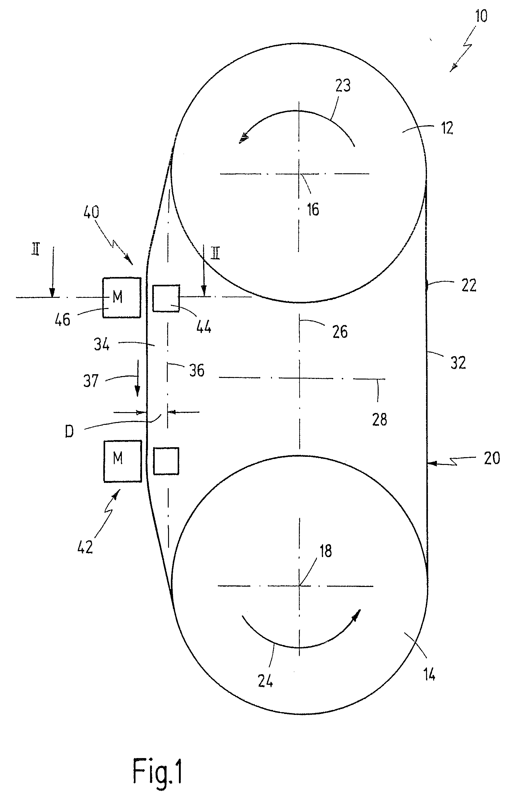
[0057]In FIG. 1, reference numeral 10 as a whole designates a band saw, as is typically used in saw mills for dissecting logs, for dissecting and edging boards and the like. Band saw 10 may be installed in the sawmill as an integrated stationary unit or as a mobile unit.

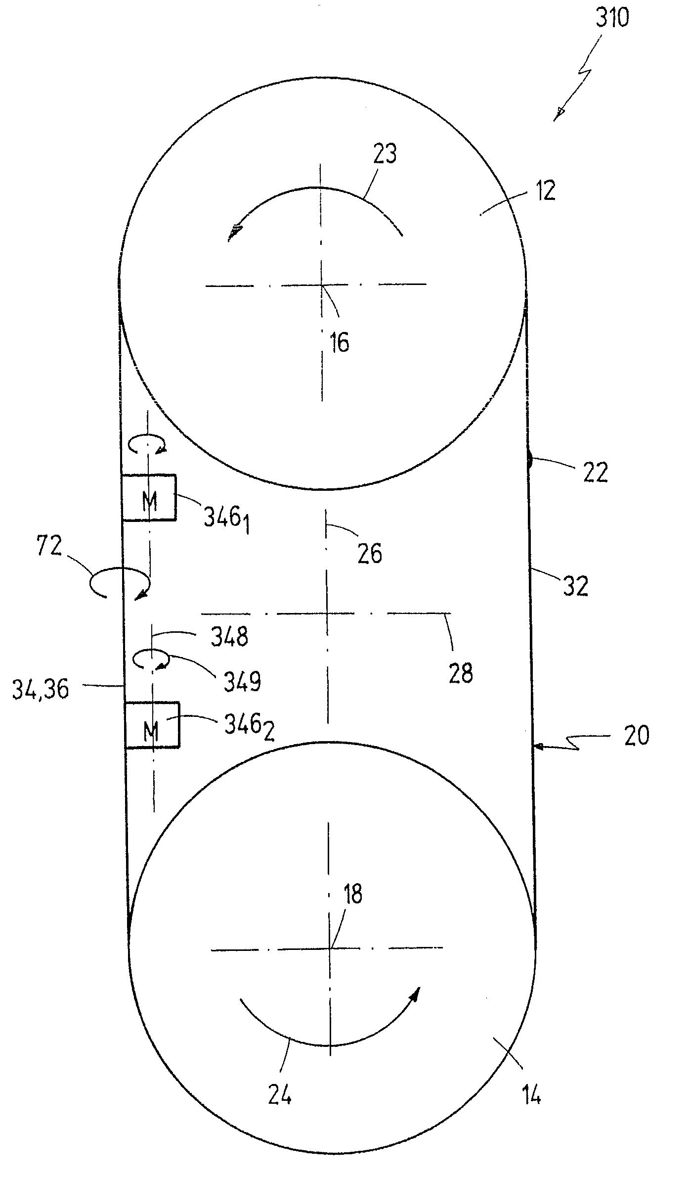
[0058]Band saw 10 comprises an upper wheel 12 and a lower wheel 14 rotating about a horizontal upper axis 16 and a lower axis 16, respectively. A band saw blade 20 is stretched over wheels 12 and 14. Band saw blade 20 is provided with teeth 21 on the front side of FIG. 1 (see FIG. 2).

[0059]The free ends of band saw blade 20 are interconnected with a butt joint 22 which may be generated by welding or soldering. With regard to band saw blade 20 butt joint 22 configures a discontinuity having the shape of a bump.

[0060]Arrows 23 and 24 indicate the sense of rotation of wheels 12 and 14. The positioning of wheels 12 and 14 with regard to a vertical axis 26 intersecting axes 16 and 18 and with regard to a horizontal axis 2...


PUM

PropertyMeasurementUnit
Forceaaaaaaaaaa
Frequencyaaaaaaaaaa

Abstract

A band saw, a band saw assembly, and a method of spatially positioning a band saw blade are suggested. The band saw comprises a band saw blade against which a sawing material is adapted to be guided in a feed direction. A guide for the band saw blade has at least one magnet exerting a force on the band saw blade determining the spatial position thereof. The at least one magnet is adjustable in its force effect and the force is directed transversely to the feed direction. The guide, as viewed in the feed direction of the sawing material, has a front magnet and a rear magnet, the magnets facing a front area and a rear area, respectively, of the band saw blade. A method of spatially positioning a band saw blade is executed while a sawing material is guided against the band saw blade in a feed direction. A magnet force is exerted on the band saw blade. The magnet force, and thereby the position of the band saw blade is adjusted transversely to the feed direction. The magnet force, as viewed in the feed direction of the sawing material, is exerted on a front area and on a rear area of the band saw blade.

Description

FIELD OF THE INVENTION[0001]The invention is related to the field of band saws and methods for positioning a band saw blade.[0002]More specifically, the invention is related to a band saw comprising a band saw blade against which a sawing material is adapted to be guided in a feed direction, and a guide for the band saw blade, the guide having at least one magnet exerting a force on the band saw blade determining the spatial position thereof, the at least one magnet being, further adjustable in its force effect and the force being directed transversely to the feed direction.[0003]Correspondingly, the invention is related to a method of spatially positioning a band saw blade while a sawing material is guided against the band saw blade in a feed direction, in which a magnet force is exerted on the band saw blade, and the magnet force, and thereby the position of the band saw blade is adjusted transversely to the feed direction.BACKGROUND OF THE INVENTION[0004]Band saws mostly consist ...

Claims


Application Information

Patent Timeline
IPC IPC(8): B27B13/00B26D3/00
CPCB23D55/084Y10T83/04Y10T83/7245Y10T83/0605
Inventor DIETZ, HANSBERGVALL, JEAN GUNNAR
Owner GEBRUEDER LINCK MASCHINENFABRIK GATTERKINCK GMBH & CO KG
Why Eureka
Try Eureka