Method for erecting a crane boom

Active Publication Date: 2009-05-21
LIEBHERR WERK EHINGEN
View PDF10 Cites 9 Cited by
  • Summary
  • Abstract
  • Description
  • Claims
  • Application Information

AI Technical Summary

Benefits of technology

[0019]In accordance with an advantageous aspect of the invention, the main boom subsequently is brought into a steep position and upon release of the spatial bracing telescoped out to the desired length. In this position, the main boom no longer is loaded so much, so that the spatial bracing can be released again in this position. The pivotally mounted end of the fly jib also is lifted, and the outer end of the fly jib is freely rolling on the at least one carriage.
[0020]Upon extending the main boom to the desired length, the telescopic stages of the main boom advantageously are bolted to each other. Subsequently, the spatial bracing advantageously is tensioned again, before the fly jib is erected. In this way, the stability of the main boom during erection of the fly jib can substantially be improved. These method steps are subject-matter of a parallel patent application of the applicants, which was filed as a German patent application with the same priority. R

Problems solved by technology

Also because of possibly disturbing edges, fly jibs are mounted on the telescopic boom in such cases.
Thus, in certain operating positions (for instance when erecting the main boom into a steep position), they can only reach the highest load moments with tensioned spatial bracing.

Method used


Image

  • Method for erecting a crane boom
  • Method for erecting a crane boom
  • Method for erecting a crane boom

Examples


Example

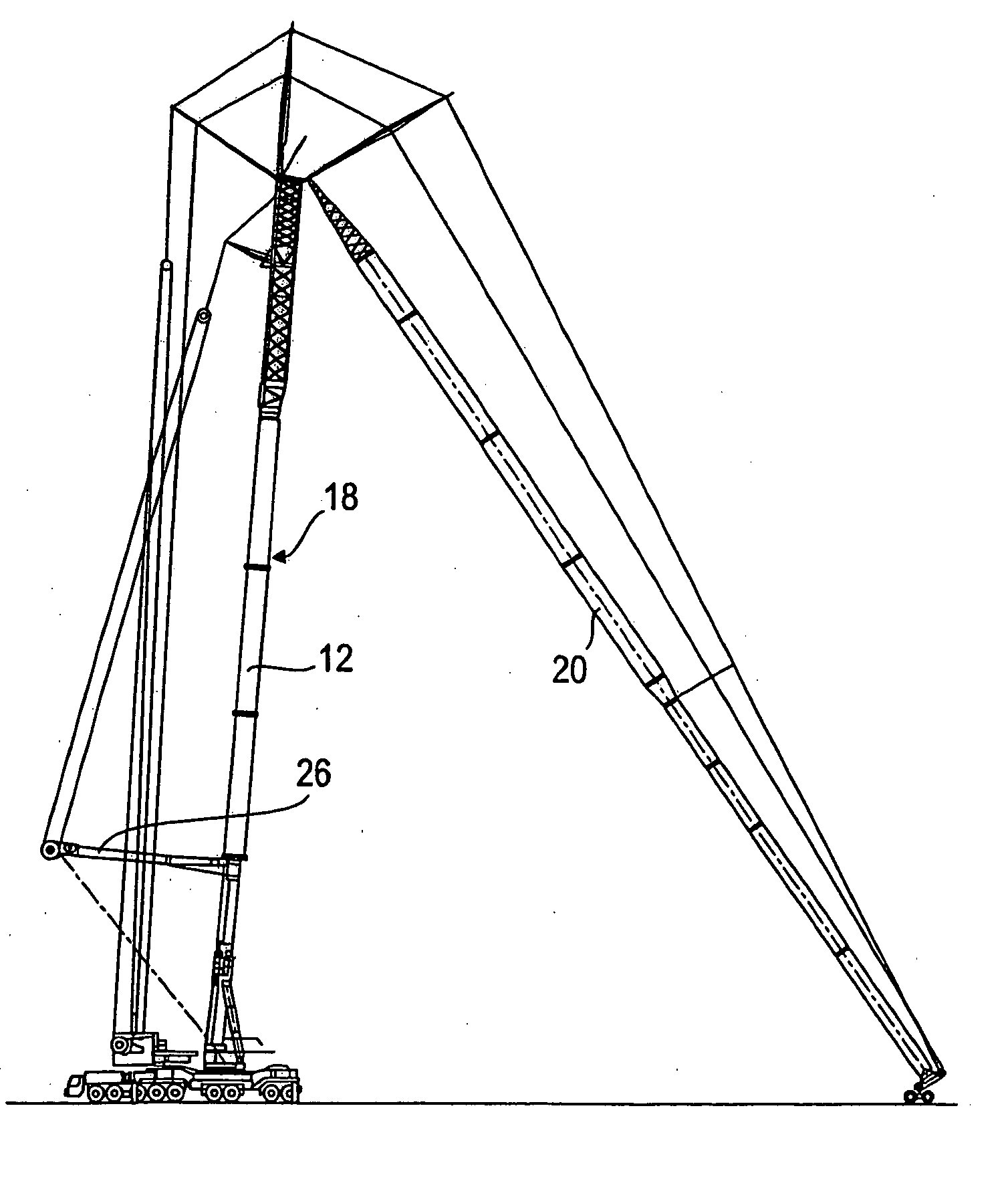
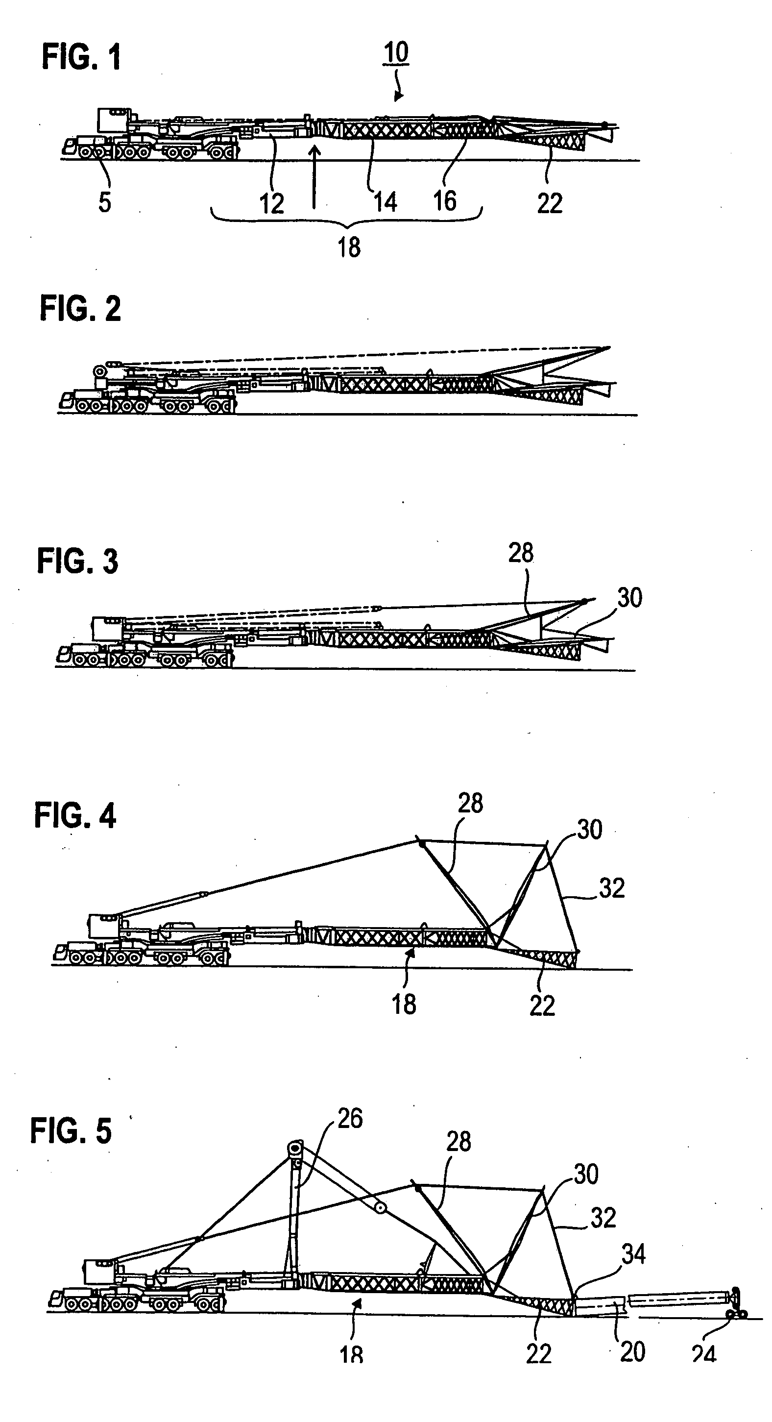
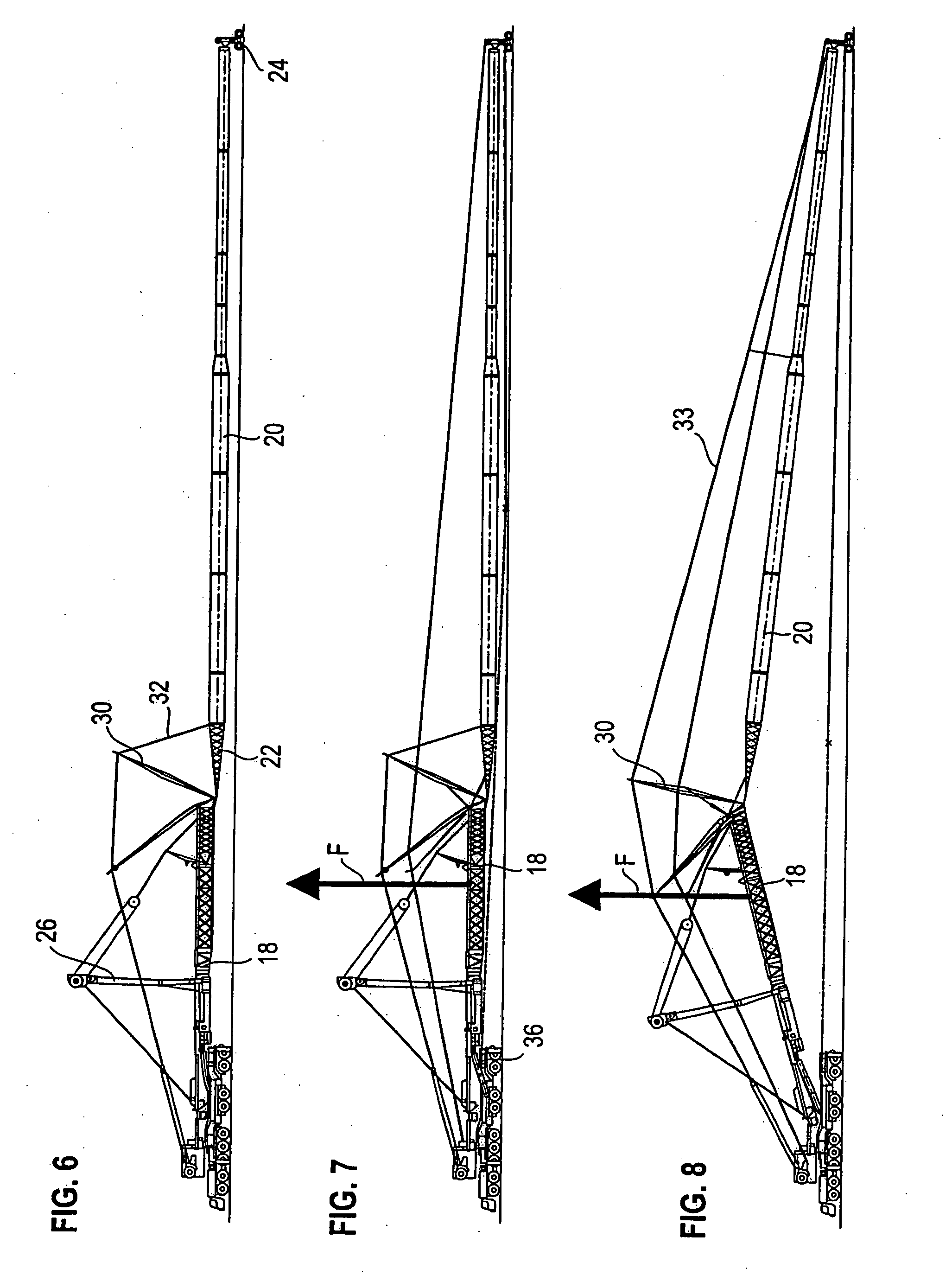
[0029]With reference to FIGS. 1 to 11, the method of the invention for erecting a crane boom 10 of a mobile crane 5 can be explained. The crane boom 10 in accordance with the embodiment shown here consists of a telescopic boom 12, a telescopic boom extension 14 and an adapter piece 16, which together form the main boom 18, and of an attached fly jib 20, which comprises a detachable foot piece 22. As is not shown in detail in the Figures, the fly jib 20 first is mounted completely without the foot piece 22, with the head piece of the fly jib 20 resting on a carriage 24.

[0030]As shown in FIG. 1, the telescopic boom 12 is connected with the telescopic boom extension 14 and the adapter piece 16. The spatial bracing 26 is mounted, but not yet tensioned. The foot piece 22 and the bracing trestles 28, 30 are attached to the main boom 18. The bracing rods 32 between the bracing trestle 30 and the end of the foot piece already are present. They are deposited on the fly jib. Finally, a connec...


PUM


Abstract

This invention relates to a method for erecting a main boom of a truck crane, which at least consists of a telescopic boom, with a fly jib which is braced via bracing trestles and bracing rods, and with a spatial boom bracing. In accordance with the invention, the main boom is braced by means of the spatial bracing before being completely connected with the fly jib.

Description

BACKGROUND OF THE INVENTION[0001]This invention relates to a method for erecting a main boom of a truck crane, which at least consists of a telescopic boom, with a fly jib which is braced via bracing trestles and bracing rods, and with a spatial boom bracing.[0002]Frequently, very high hoisting heights and outreaches are required. The same go beyond the working ranges of telescopic cranes. Also because of possibly disturbing edges, fly jibs are mounted on the telescopic boom in such cases. The fly jibs can achieve very great lengths, which even can extend far beyond the length of the main boom itself. Such fly jibs can consist of a luffing jib or a fixed jib. When using correspondingly long fly jibs, it is absolutely necessary to provide bracing trestles and bracing rods, which extend from the bracing trestle to the tip of the fly jib.[0003]In the case of high disturbing edges, hoisting heights of up to 170 m are achieved. With such long boom systems, a spatial bracing regularly is ...

Claims


Application Information

Patent Timeline
IPC IPC(8): B66C23/687
CPCB66C23/82B66C13/06B66C23/702
Inventor WILLIM, HANS-DIETER
Owner LIEBHERR WERK EHINGEN
Why Eureka
Try Eureka