Hard disk drive tunneling magnetoresistive annealing heads with a fly on demand heater

magnetoresistive technology, applied in the field of recovering data from the disk of a hard disk drive, can solve problems such as data errors that cannot be recovered, transient errors that occur, and errors that may occur when reading data from the disk

Inactive Publication Date: 2009-05-21
SAMSUNG ELECTRONICS CO LTD
View PDF5 Cites 14 Cited by
  • Summary
  • Abstract
  • Description
  • Claims
  • Application Information

AI Technical Summary

Problems solved by technology

Errors may occur when reading data from the disk.
Such schemes typically recover transient errors that occur during the write or read operations of the drive.
Structural defects in drive components may cause data errors that cannot be recovered.
The residual aluminum degrades the performance of the heads and cause errors in the writing of data.

Method used


Image

  • Hard disk drive tunneling magnetoresistive annealing heads with a fly on demand heater
  • Hard disk drive tunneling magnetoresistive annealing heads with a fly on demand heater
  • Hard disk drive tunneling magnetoresistive annealing heads with a fly on demand heater

Examples


Embodiment Construction

[0014]Disclosed is a hard disk drive that includes a head coupled to a disk. The head has a heater element. The drive also includes a controller that causes the heater element to heat the head to a temperature sufficient to anneal material within the head. The head is heated to a temperature sufficient to transform residual aluminum into aluminum oxide. This heating process preferably occurs while the drive is not writing or reading data and the head is off disk.

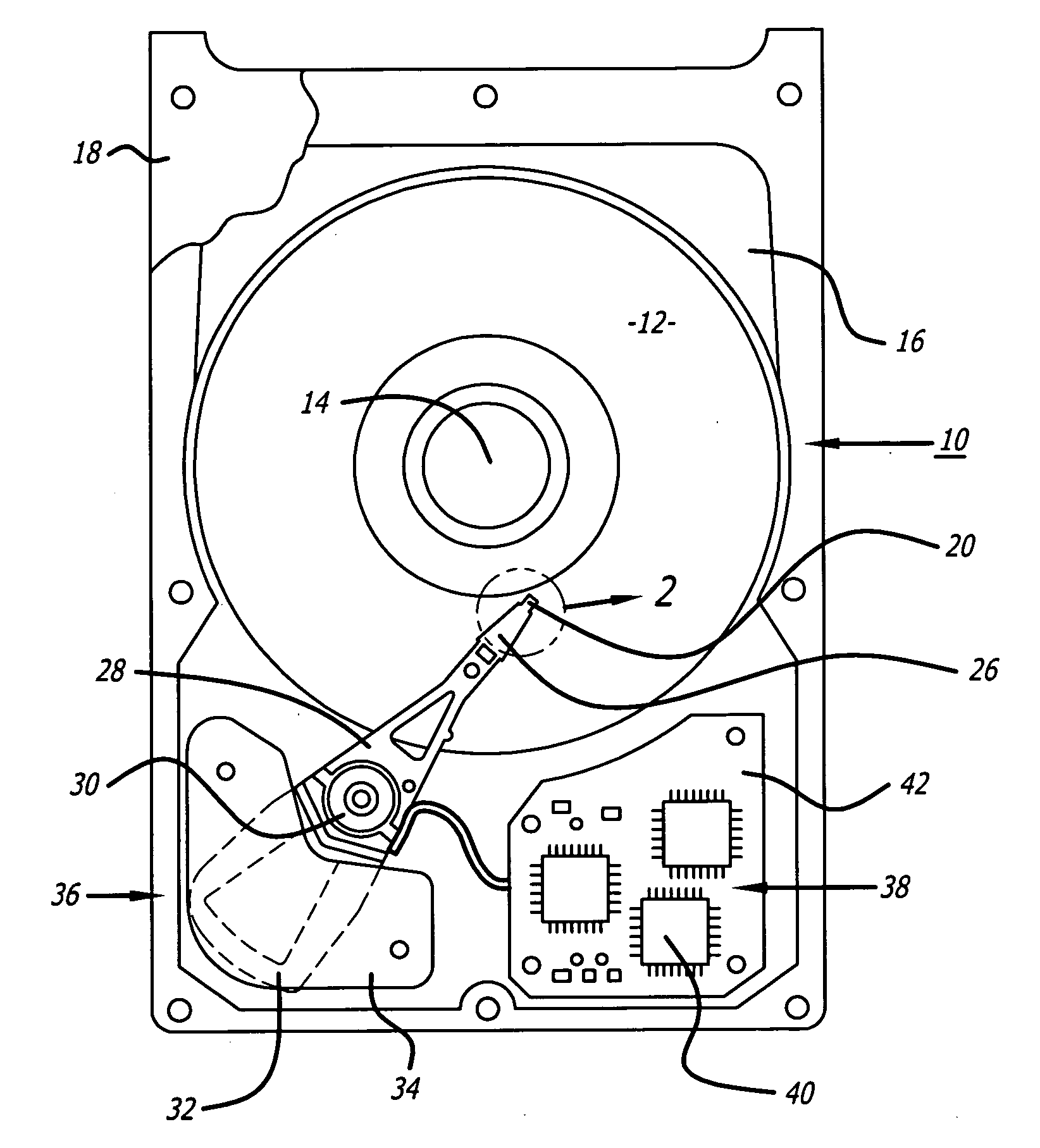
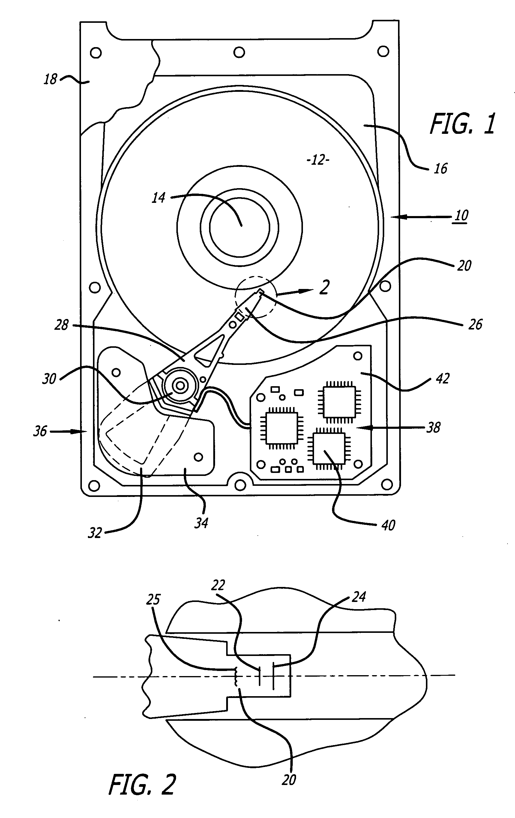
[0015]Referring to the drawings more particularly by reference numbers, FIG. 1 shows an embodiment of a hard disk drive 10 of the present invention. The disk drive 10 may include one or more magnetic disks 12 that are rotated by a spindle motor 14. The spindle motor 14 may be mounted to a base plate 16. The disk drive 10 may further have a cover 18 that encloses the disks 12.

[0016]The disk drive 10 may include a plurality of heads 20 located adjacent to the disks 12. As shown in FIG. 2 the heads 20 may have separate write 22...


PUM

PropertyMeasurementUnit
temperatureaaaaaaaaaa
magnetic fieldsaaaaaaaaaa

Abstract

A hard disk drive that includes a head coupled to a disk. The head has a heater element. The drive also includes a controller that causes the heater element to heat the head to a temperature sufficient to anneal material within the head. The head is heated to a temperature sufficient to cause oxidation of any metal, such as aluminum, within the head, and/or oxygen redistribution and homogenization in the barrier. This heating process preferably occurs while the drive is not writing or reading data and the head is off disk.

Description

BACKGROUND OF THE INVENTION[0001]1. Field of the Invention[0002]The present invention relates to recovering data from a disk of a hard-disk drive.[0003]2. Background Information[0004]Hard disk drives contain a plurality of magnetic heads that are coupled to rotating disks. The heads write and read information by magnetizing and sensing the magnetic fields of the disk surfaces. Each head is attached to a flexure arm to create a subassembly commonly referred to as a head gimbal assembly (“HGA”). The HGA's are suspended from an actuator arm. The actuator arm has a voice coil motor that can move the heads across the surfaces of the disks.[0005]The disks are rotated by a spindle motor of the drive. Rotation of the disks creates an air flow within the disk drive. Each head has an air bearing surface that cooperates with the air flow to create an air bearing between the head and the adjacent disk surface. The air bearing eliminates or minimizes the mechanical wear between the head and the ...

Claims


Application Information

Patent Timeline
Patent Type & Authority Applications(United States)
IPC IPC(8): G11B5/09
CPCG11B5/40G11B5/41G11B5/6005G11B2220/2516G11B20/18G11B2005/001G11B5/6064G11B5/607
Inventor JANG, EUNKYUMOON, KISEOK
Owner SAMSUNG ELECTRONICS CO LTD
Why Eureka
Try Eureka