Access door for gas turbine engine components

a technology for gas turbine engines and access doors, which is applied in the direction of machines/engines, liquid fuel engines, power plant inspection panels, etc., can solve the problems of insufficient size of access doors to allow maintenance, and cumbersome and time-consuming

Active Publication Date: 2009-05-21
RAYTHEON TECH CORP
View PDF17 Cites 23 Cited by
  • Summary
  • Abstract
  • Description
  • Claims
  • Application Information

AI Technical Summary

Problems solved by technology

This is somewhat cumbersome and time consuming, particularly when required for routine maintenance to an internal component such as the gear box or an electrical genera

Method used


Image

  • Access door for gas turbine engine components
  • Access door for gas turbine engine components
  • Access door for gas turbine engine components

Examples


embodiment 130

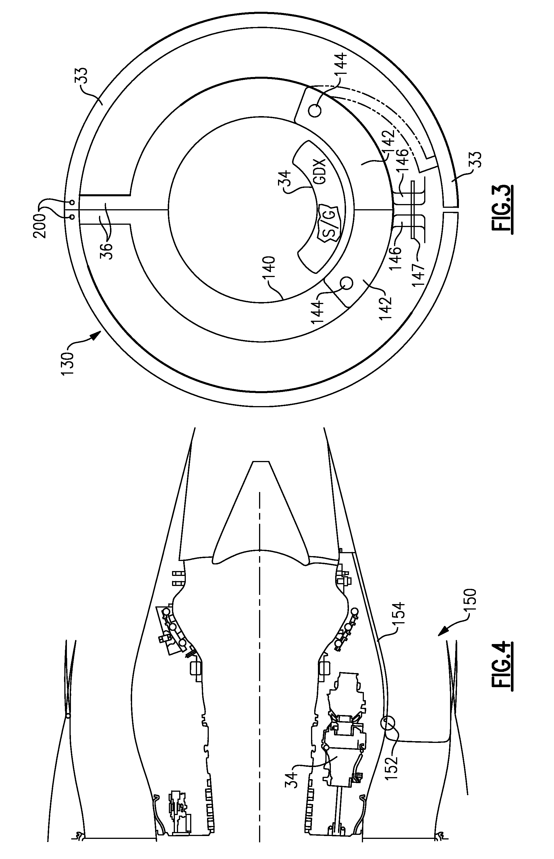
[0014]The present invention is directed to simplifying the amount of work necessary to gain access to the internal components 34. Thus, as shown in FIG. 3, in an embodiment 130, access doors 142 are pivotally attached at 144 to housing portion 140. That is, the prior art housing portion 40 may be changed to include portion 140 and access door 142. Some latching element 147 may latch two tangs 146 on the housing portions 142. As shown schematically, the entire fan duct door pivots about axis 200. Without needing to pivot the entire fan duct, the access door 142 may be pivoted to an open position (as shown in phantom) to provide access to the internal components 34. The present invention is particularly feasible in gas turbine engines having shorter nacelles, such that the location of the components 34 tends to be closer to the axial location of the end of the nacelle.

embodiment 150

[0015]FIG. 4 shows another embodiment 150, wherein the access door 154 pivots about a hinge axis 152 extending generally perpendicular to the axis of the hinges 144 of the FIG. 3 embodiment. That is, axis 152 is perpendicular to an axis that is parallel to the central axis 22.

[0016]In the prior art it is known to provide access doors for various functions such as access to lubrication system, etc. However, these access doors have not been provided to facilitate the maintenance and removal of internal components such as the auxiliary gear box or generator.

[0017]While the access doors in FIGS. 3 and 4 are shown as being pivotably attached, they could be simply removable, and secured in some appropriate manner.

[0018]When it is desired to merely access the auxiliary components such as the auxiliary gear box or electrical generator, the access door may be opened, and the fan duct doors may remain closed. At this position, there is access to the components for maintenance or removal. The ...


PUM


Abstract

An access door is provided in a housing for a gas turbine engine, with the access door being movable to an access position independent of any required movement of any cowl door or a fan duct door.

Description

BACKGROUND OF THE INVENTION[0001]This application relates to an access door provided in an inner housing of a gas turbine engine to provide access to internal components, without the need to open the cowl or fan duct doors.[0002]Gas turbine engines are known, and often include a fan delivering air to a compressor. Air is compressed in the compressor and delivered downstream to be mixed with fuel and combusted in a combustion section. Products of this combustion pass over turbine rotors, and drive the turbine rotors to rotate. A portion of the air delivered by the fan passes into a bypass duct about an engine core and is not delivered to the compressor. This air provides the majority of thrust for such a gas turbine engine.[0003]A nacelle surrounds the fan, and defines the bypass duct with an inner housing. The inner housing surrounds the engine core. Typically fan cowl doors, and fan duct / thrust reverser doors (hereafter “fan duct doors”) are provided in the nacelle. These doors may...

Claims


Application Information

Patent Timeline
IPC IPC(8): F01D25/28
CPCB64D29/08F01D25/24F05D2250/30F05D2240/14F05D2240/90F02K3/06
Inventor CLOFT, THOMAS G.GUKEISEN, ROBERT L.
Owner RAYTHEON TECH CORP
Why Eureka
Try Eureka