
Bipolar forceps

a technology of bipolar forceps and forceps, which is applied in the field of bipolar forceps, can solve the problems of unreliability or inoperative surgical instruments, and achieve the effect of reducing the likelihood of wire damage or broken

Active Publication Date: 2009-05-21
ETHICON ENDO SURGERY INC
View PDF102 Cites 87 Cited by
  • Summary
  • Abstract
  • Description
  • Claims
  • Application Information

AI Technical Summary

Benefits of technology

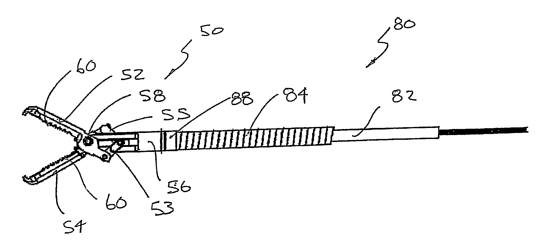
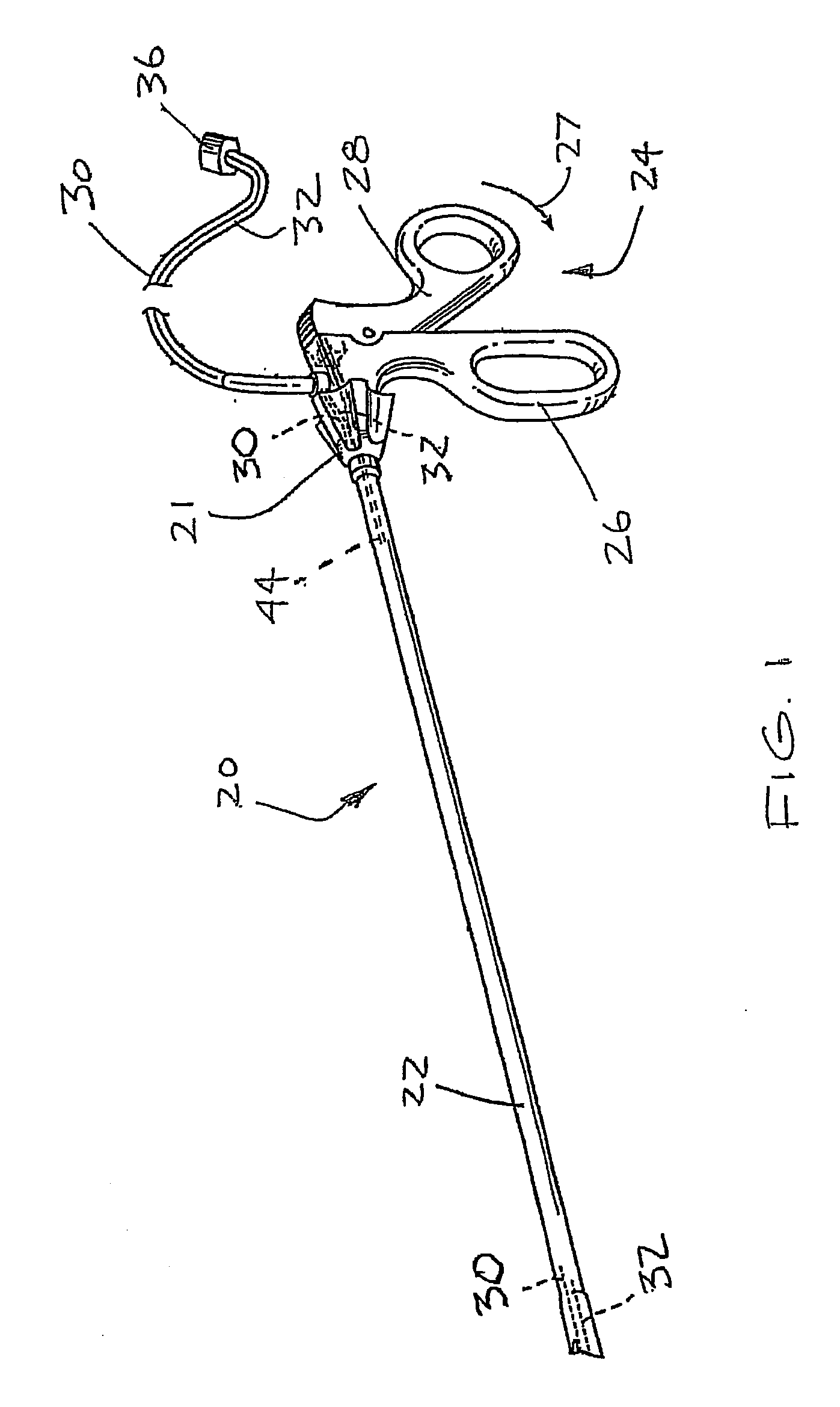
[0006]In at least one form of the invention, a bipolar forceps can include a first electrode, a second electrode, and a conductor, or wire, operably connected to an electrical source, for example, wherein the conductor can be selectively placed in electrical communication with the first electrode when the first electrode is moved between open and closed positions. In various embodiments, the wire can include a contact end which is not in contact with the first electrode when the first electrode is in its open position. In such an open position, the first electrode may not be in electrical communication with the electrical source and, as a result, current may not flow through the first electrode. In at least one such embodiment, the first electrode can be moved into its closed position such that the first electrode is in contact with the contact end of the wire. In such a closed position, the first electrode may be in electrical communication with the electrical source allowing current to flow through the first electrode. As a result of the above, the first electrode can move relative to the wire such that the wire does not have to move with the first electrode when the first electrode is moved between its open and closed positions and, as a result, the likelihood that the wire may become damaged or broken can be reduced.

Problems solved by technology

In some circumstances, such bending or stretching may cause the wire to break and / or the insulation covering the wire to become chaffed, thereby rendering the surgical instrument inoperative or unreliable.

Method used


Image

  • Bipolar forceps
  • Bipolar forceps
  • Bipolar forceps

Examples


Embodiment Construction

[0035]Certain exemplary embodiments will now be described to provide an overall understanding of the principles of the structure, function, manufacture, and use of the devices and methods disclosed herein. One or more examples of these embodiments are illustrated in the accompanying drawings. Those of ordinary skill in the art will understand that the devices and methods specifically described herein and illustrated in the accompanying drawings are non-limiting exemplary embodiments and that the scope of the various embodiments of the present invention is defined solely by the claims. The features illustrated or described in connection with one exemplary embodiment may be combined with the features of other embodiments. Such modifications and variations are intended to be included within the scope of the present invention.

[0036]The various embodiments described herein are related to electrical therapy ablation devices. Generally, electrical therapy ablation devices can comprise elec...


PUM


Abstract

A bipolar forceps including a first electrode, a second electrode, and a conductor operably connected to an electrical source, wherein the conductor can be selectively placed in electrical communication with the first electrode when the first electrode is moved between open and closed positions. The conductor can include a contact end which is not in contact with the first electrode when the first electrode is in its open position. In such an open position, the first electrode may not be in electrical communication with the electrical source and, as a result, current may not flow through the first electrode. The first electrode can be moved into its closed position such that the first electrode is in contact with the contact end of the wire. In such a closed position, the first electrode may be in electrical communication with the electrical source allowing current to flow through the first electrode.

Description

RELATED APPLICATION[0001]The present application is related to U.S. patent application Ser. No. ______, entitled BIPOLAR FORCEPS HAVING A CUTTING ELEMENT, Atty. Docket No. END6184USNP1 / 070467, which is a commonly-owned U.S. patent application filed concurrently herewith, the entire disclosure of which is hereby incorporated by reference herein.BACKGROUND[0002]1. Field of the Invention[0003]The present invention generally relates to electrical ablation surgical instruments and, more particularly, to bipolar forceps for performing various surgical techniques.[0004]2. Description of the Related Art[0005]Previous bipolar forceps have included a grasping device which is configured to grasp and manipulate soft tissue, for example. In various circumstances, the grasping device has included a first electrode and a second electrode where, when one of the electrodes is brought into close opposition to the other electrode, an electrical current can pass therebetween. More particularly, when so...

Claims


Application Information

Patent Timeline
IPC IPC(8): A61B18/14
CPCA61B18/1445
Inventor GHABRIAL, RAGAE M.VAKHARIA, OMAR J.
Owner ETHICON ENDO SURGERY INC
Learn More