
Enhanced Rail Inspection

a technology of rail inspection and enhanced inspection, applied in the direction of fire alarms, ways, instruments, etc., can solve the problems of imposing a limit on the speed of trains, affecting the resolution of obtained data, and affecting the safety of passengers or bystanders

Inactive Publication Date: 2009-05-21
TAIWAN SEMICON MFG CO LTD
View PDF9 Cites 41 Cited by
  • Summary
  • Abstract
  • Description
  • Claims
  • Application Information

AI Technical Summary

Benefits of technology

This patent describes a new way to inspect rail systems by using a mobile device called a monitor vehicle. This vehicle can run along different parts of the rail system and use special tools to check its condition without causing any damage. It measures things like how much heat there is on the track and checks if it's been bent or damaged during previous usage. By analyzing this data and identifying specific issues, the monitor vehicle can alert people about potential hazards before they become serious. Overall, this technology helps make sure that rails remain safe and reliable.

Problems solved by technology

The technical problem addressed in this patent text relates to developing a better method for inspecting rails in rail systems, particularly those used in industrial facilities where materials handling takes place. Current methods involve slow inspections that limit training opportunities and increase labor costs, resulting in lower efficiency and potential safety issues. Additionally, existing solutions fail to monitor all relevant data and power transfer mechanisms simultaneously, leading to further limitations in detecting flaws early enough to prevent accidents or breakdowns.

Method used


Image

  • Enhanced Rail Inspection
  • Enhanced Rail Inspection
  • Enhanced Rail Inspection

Examples


Embodiment Construction

[0022]The making and using of the presently preferred embodiments are discussed in detail below. It should be appreciated, however, that the present invention provides many applicable inventive concepts that can be embodied in a wide variety of specific contexts. The specific embodiments discussed are merely illustrative of specific ways to make and use the invention, and do not limit the scope of the invention.

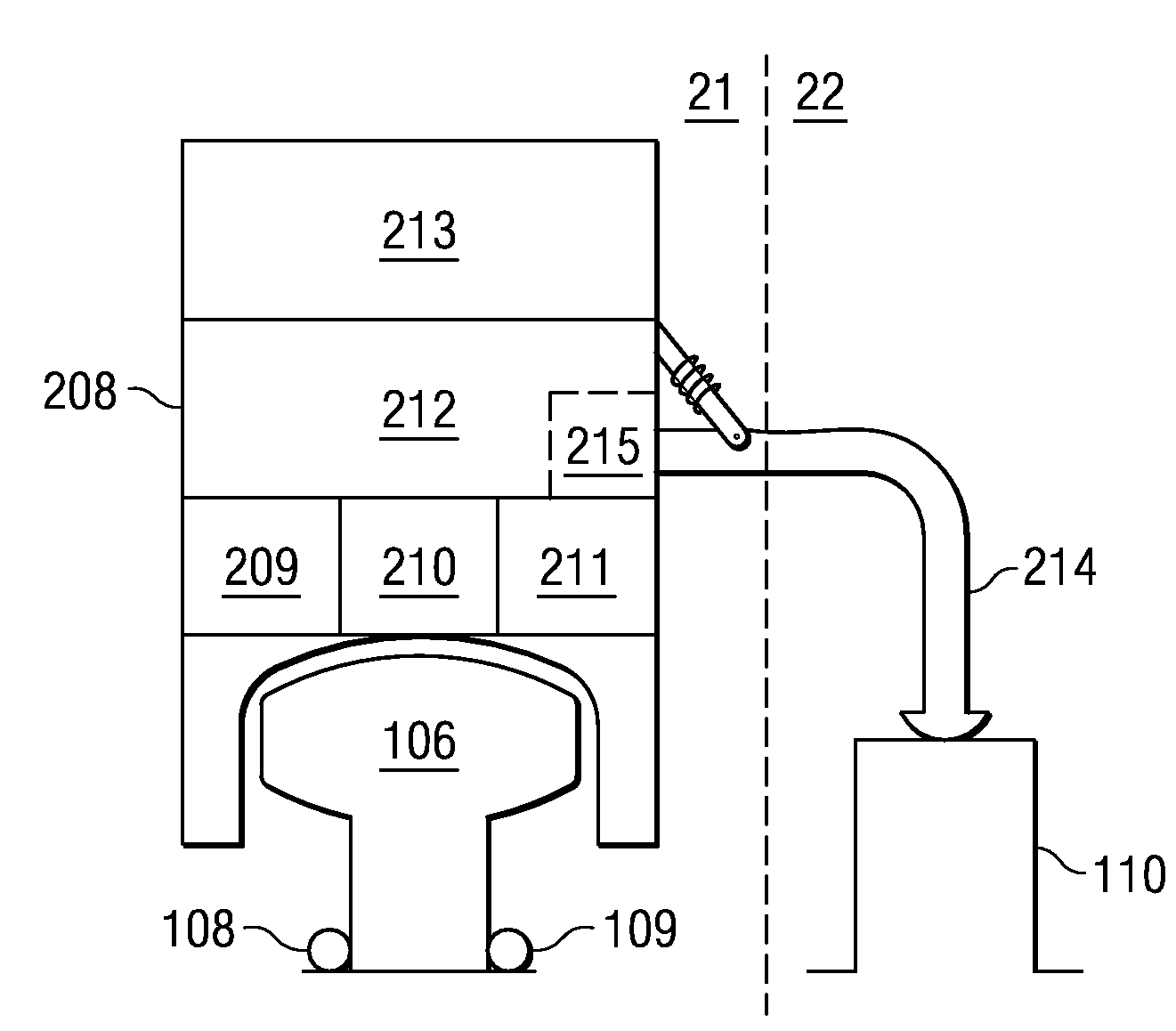
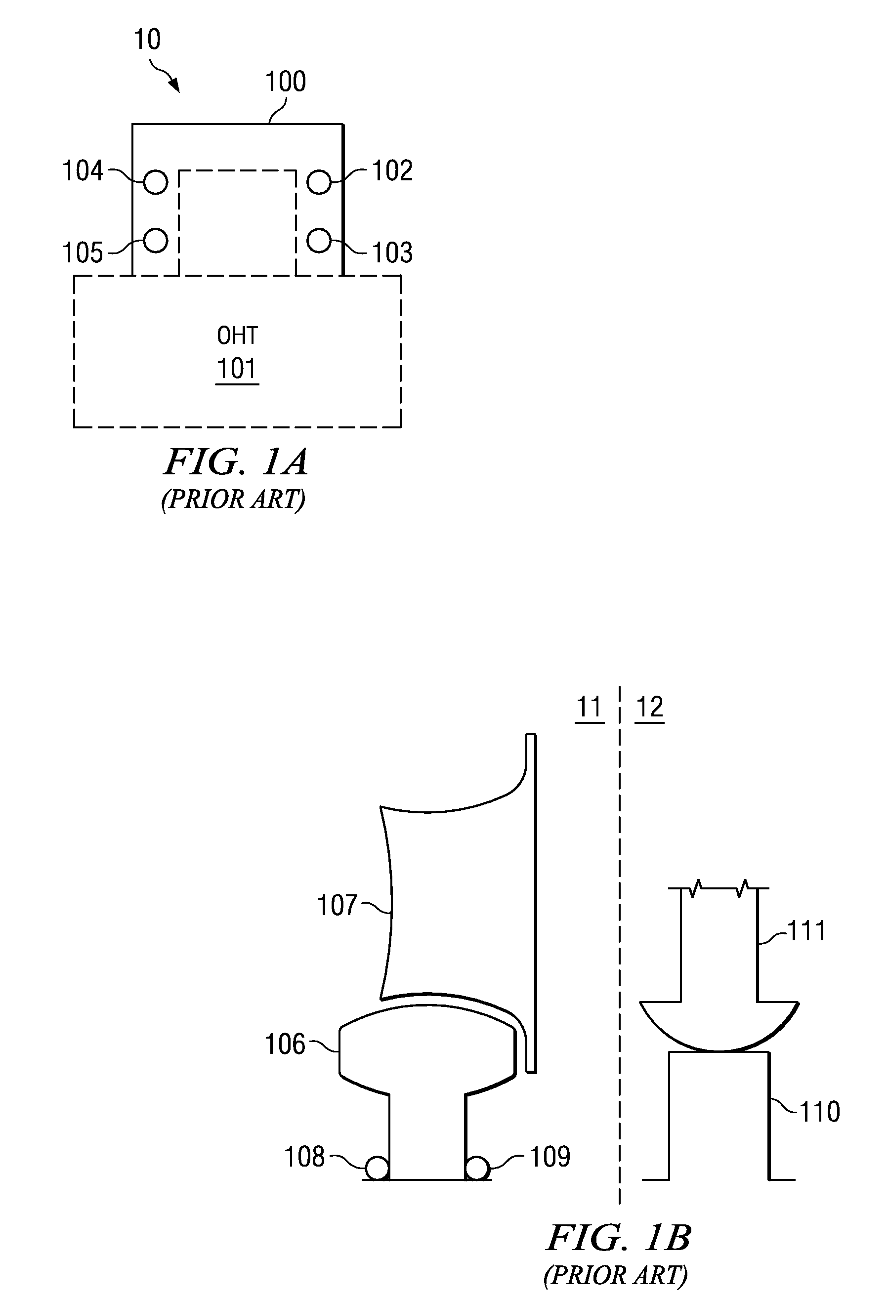
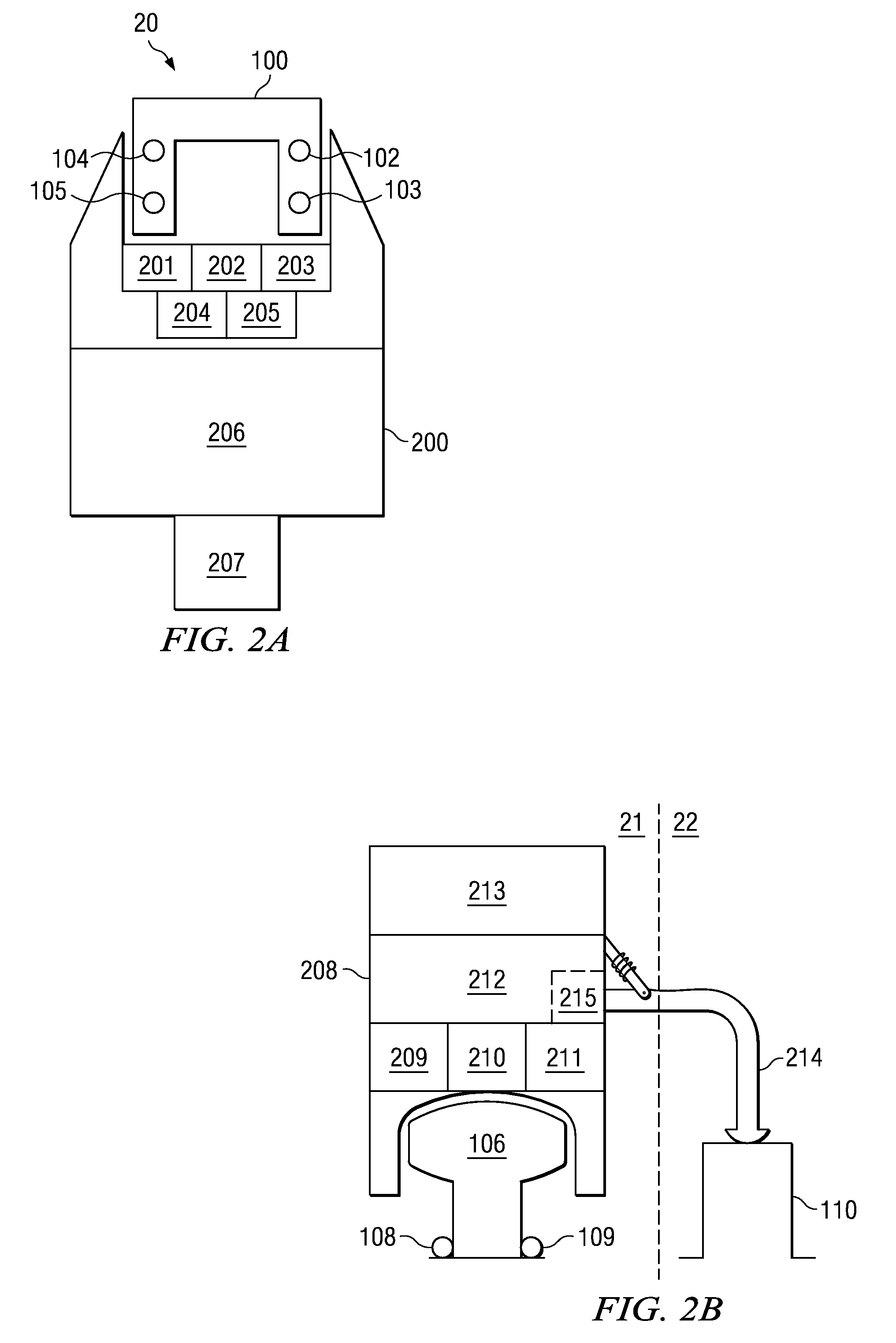
[0023]FIG. 1A is a diagram illustrating typical over-head rail configuration 10. Rail 100 provides a connection point for over-head train (OHT) 101. The configuration of rail 100 includes power lines 102 and 104 and communication lines 103 and 105. Power lines 102 and 104 provide power for OHT 101 to move over rail 100. Communication lines 103 and 105 provide a path for communication signals which may be used both for providing communication information to OHT 101 regarding operation, such as a path, speed, direction, and the like, and may also provide a conduit for general c...


PUM


Abstract

Rail inspection is discussed that employs a monitor vehicle running on one or more tracks of a rail system that performs physical rail inspection in combination with monitoring and analysis of other system parameters that accompany the physical rail.

Description


Claims


Application Information

Patent Timeline
Owner TAIWAN SEMICON MFG CO LTD
Learn More