Maintenance planning system and maintenance planning method

a maintenance planning and maintenance technology, applied in the field of maintenance planning system and maintenance planning method, can solve the problems of increasing maintenance cost, reducing product life, and reducing product life, so as to minimize a predetermined cost, the effect of minimizing a predetermined cos

Inactive Publication Date: 2009-05-21
KK TOSHIBA +1
View PDF4 Cites 33 Cited by
  • Summary
  • Abstract
  • Description
  • Claims
  • Application Information

AI Technical Summary

Benefits of technology

[0006]The present invention is intended to provide a maintenance planning system and a maintenance planning method for calculating a combination for optimizing the time interval of visiting for maintenance for each product and the time interval of replacement of each consumable part and forming an operation plan, thereby taking the balance between risk and cost into account for a plurality of products.
[0007]The maintenance planning system of an embodiment of the present invention is comprised a counter value acquiring unit to acquire a counter value indicating use results of consumable parts of a plurality of apparatuses that are maintenance targets; an interval information acquiring unit, among information related to a combination of a visit interval to specify a time interval to visit installation places of the plurality of apparatuses that are maintenance targets to perform a maintenance check operation for the plurality of apparatuses that are maintenance targets with a replacement interval specified to replace each consumable part and associated with the visit interval, to acquire a combination of the visit interval and the replacement interval for minimizing a predetermined cost for each consumable part of the plurality of apparatuses that are maintenance targets; a maintenance plan creation unit, on the basis of the minimized visit interval and replacement interval acquired by the interval information acquiring unit and the counter value acquired by the counter value acquiring unit, to identify the apparatus that is a maintenance target to be visited next, timing of next visit, and a consumable part to be replaced at the timing; and a display unit to display information identified by the maintenance plan creation unit on a terminal.
[0008]Furthermore, the maintenance planning system of an embodiment of the present invention is comprised counter value acquiring means for acquiring a counter value indicating use results of consumable parts of a plurality of apparatuses that are maintenance targets; interval information acquiring means, among information related to a combination of a visit interval for specifying a time interval for visiting installation places of the plural

Problems solved by technology

The conventional maintenance plan cannot balance the user's damage risk caused by unavailability of a product with the cost charged for maintenance.
Therefore, the component replacement operation must be performed and managed in safety, thus a problem arises that the maintenance cost is increased.
On the other hand, if it is intended to

Method used


Image

  • Maintenance planning system and maintenance planning method
  • Maintenance planning system and maintenance planning method
  • Maintenance planning system and maintenance planning method

Examples


first embodiment

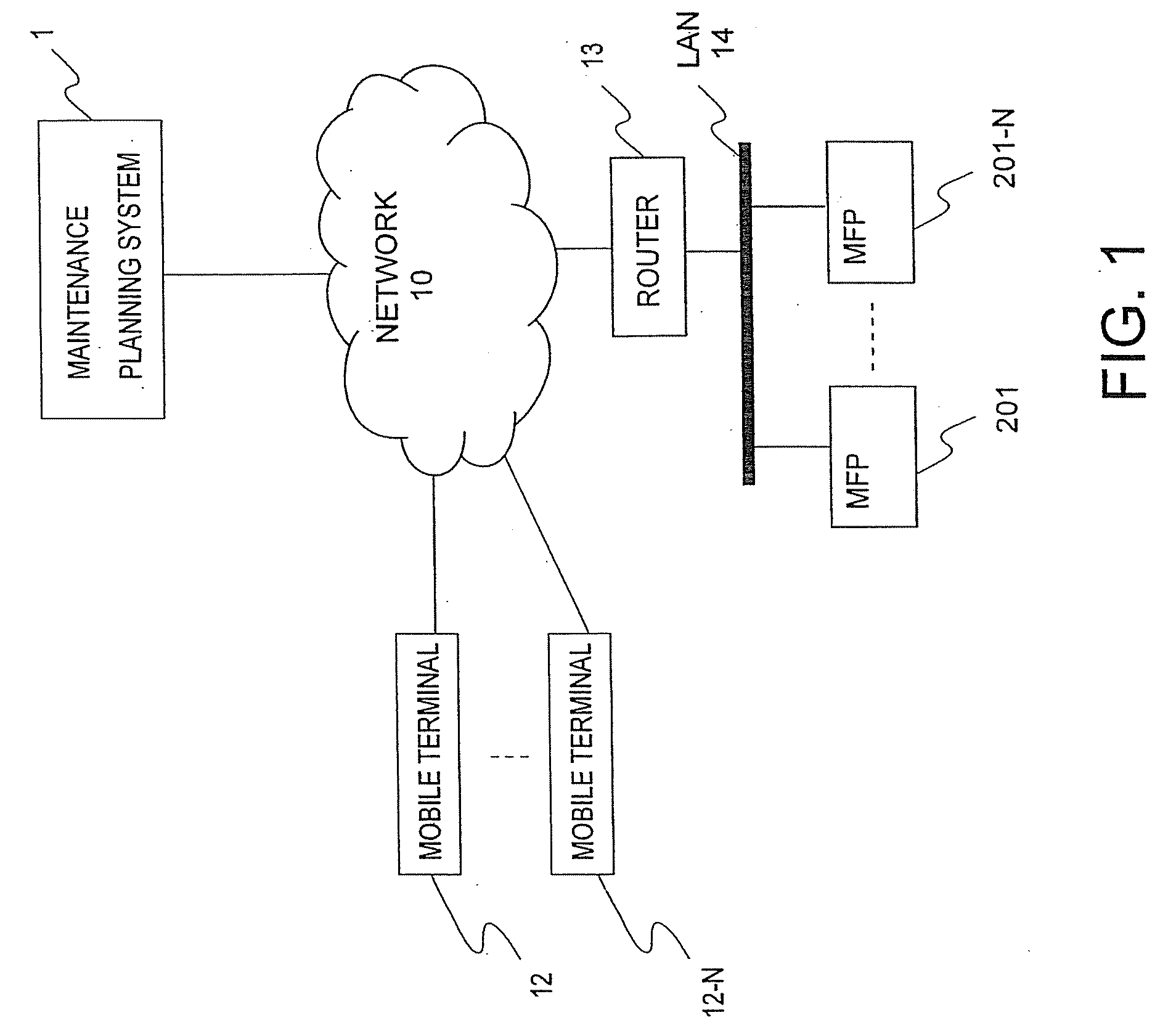
[0026](First embodiment) FIG. 1 is a drawing showing the relationship of a communication system between the maintenance planning system relating to the embodiments of the present invention and a product that is maintenance target. The maintenance planning system 1 is connected to various terminals via a network 10. The various terminals, for example, may be considered to be a plurality of MFPs 201 to 201-N and a plurality of mobile terminals 12 to 12-N.

[0027]Namely, the maintenance planning system 1 is connected to the network 10 and acquires the information relating to the use status and maintenance history of the MFPs 201 to 201-N. On the basis of these information, the maintenance planning system 1 forms a maintenance plan and via the network 10, transmits the information of the maintenance plan formed to the MFPs 201 to 201-N and the mobile terminals 12 to 12-N possessed by a serviceman. The mobile terminals 12 to 12-N and MFPs 201 to 201-N receiving the maintenance plan informa...

second embodiment

[0086](Second embodiment) This embodiment, in the “visit date indicating mode”, periodically executes calculations for all a plurality of machines entered beforehand.

[0087]The maintenance plan unit 206 has a schedule function executed periodically (for example, at 6 o'clock everyday), executes the “visit date indicating mode” of all users entered in the “user” table 301 shown in FIG. 5, and updates the “visit plan” table 311 shown in FIG. 5. The serviceman 202, when he comes to office, using the mobile communication terminals 12 to 12-N from the operation output unit of the service center terminal 208 or outside the company, accesses the maintenance planning system 1, inputs his ID, and asks the maintenance schedule. The maintenance plan unit 206 checks the input ID with the “serviceman. ID” of the “machine” table 304 and extracts all the tuples of the coinciding “machine” table 304. Furthermore, it checks the “IDs” of all the extracted tuples with the “machine. ID” of the “visit pl...


PUM


Abstract

A maintenance planning system comprises a counter value acquiring unit to acquire a counter value indicating use results of consumable parts of a plurality of apparatuses that are maintenance targets; an interval information acquiring unit, among information related to a combination of a visit interval to specify a time interval to visit installation places of the plurality of apparatuses that are maintenance targets to perform a maintenance check operation for the plurality of apparatuses that are maintenance targets with a replacement interval specified to replace each consumable part and associated with the visit interval, to acquire a combination of the visit interval and the replacement interval for minimizing a predetermined cost for each consumable part of the plurality of apparatuses that are maintenance targets; a maintenance plan creation unit, on the basis of the minimized visit interval and replacement interval acquired by the interval information acquiring unit and the counter value acquired by the counter value acquiring unit, to identify the apparatus that is a maintenance target to be visited next, timing of next visit, and a consumable part to be replaced at the timing; and a display unit to display information identified by the maintenance plan creation unit on a terminal.

Description

CROSS-REFERENCE TO RELATED APPLICATION[0001]This application is based upon and claims the benefit of priority from the prior U.S. Patent Application No. 60 / 988,339, filed on Nov. 15, 2007, and Japanese Patent Application No. 2008-151796, filed on Jun. 11, 2008; the entire contents of all of which are incorporated herein by reference.FIELD OF THE INVENTION[0002]The present invention relates to a maintenance planning system and a maintenance planning method for inferring the failure time of an image forming apparatus having a plurality of consumable parts and the deterioration degree of each component and reflecting it on the maintenance plan.DESCRIPTION OF THE BACKGROUND[0003]The conventional maintenance plan cannot balance the user's damage risk caused by unavailability of a product with the cost charged for maintenance. To reduce the product failure risk, it is necessary to foresee a component having high possibility of failure and replace it before the failure or replace it before...

Claims


Application Information

Patent Timeline
IPC IPC(8): G06Q10/00
CPCG06Q10/06G06Q10/06313G06Q10/06312
Inventor KAMISUWA, YOSHIKATSUNAKANE, RINTAROKATOU, HIROYO
Owner KK TOSHIBA
Why Eureka
Try Eureka