Data storage apparatus and data storage method
a data storage and data technology, applied in the field of recording data, can solve the problems of lowering the writing efficiency, and achieve the effect of improving the data writing efficiency
- Summary
- Abstract
- Description
- Claims
- Application Information
AI Technical Summary
Benefits of technology
Problems solved by technology
Method used
Image

Examples
first embodiment
A. First Embodiment
(A1) General Configuration of Data Storage Apparatus
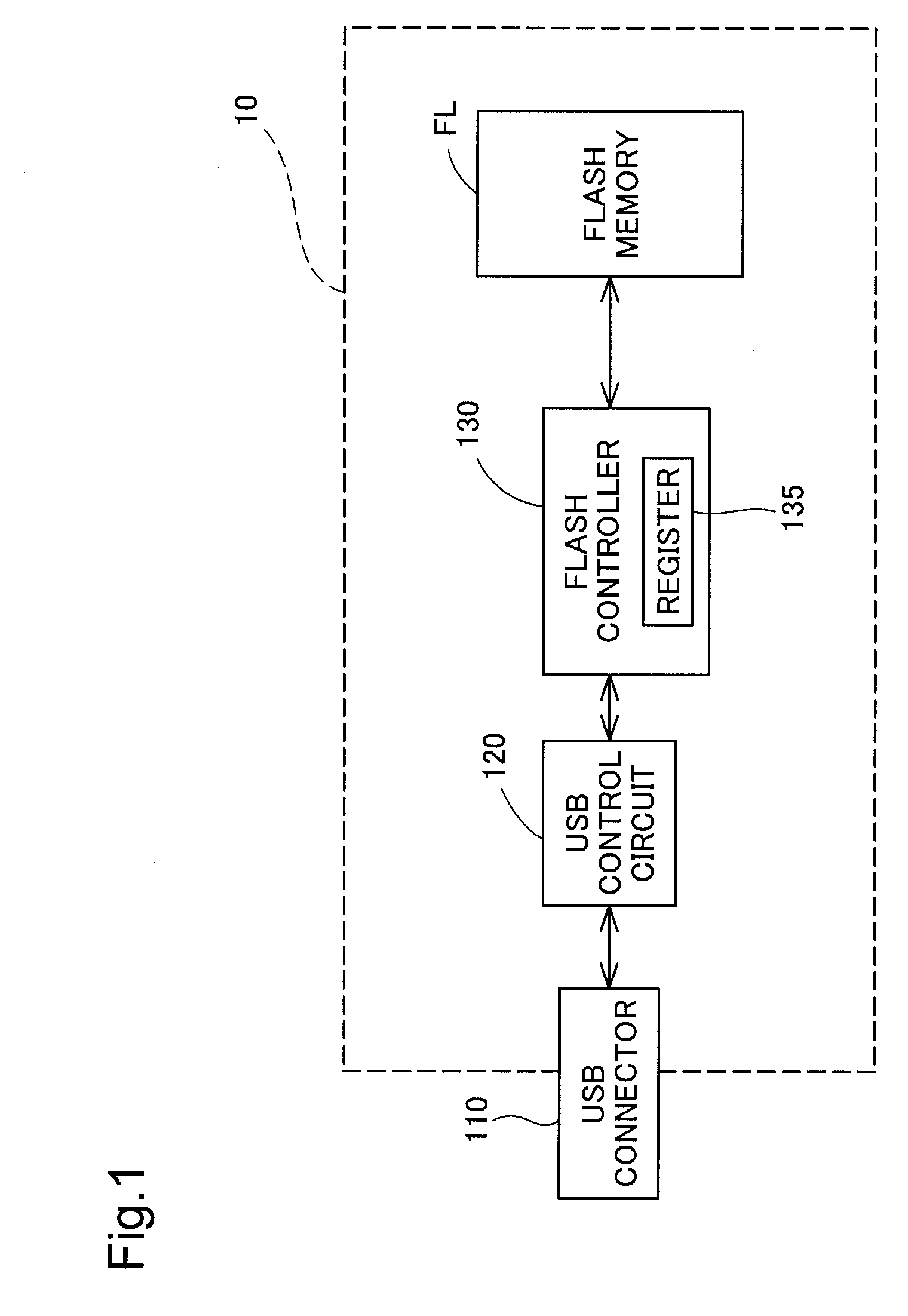
[0049]FIG. 1 is an explanatory view showing the schematic configuration of a data storage apparatus 10 in a first embodiment. As illustrated, the data storage apparatus 10 of the embodiment includes a USB connector 110, a USB control circuit 120, a flash controller 130, and a flash memory FL.
[0050]The USB connector 110 is exposed on a casing of the data storage apparatus 10 (expressed by a broken line rectangle in the drawing) and is connected to a USB interface provided in a host device, such as a personal computer or a printer.
[0051]The USB control circuit 120 is connected with the USB connector 110 and with the flash controller 130. The USB control circuit 120 causes the data storage apparatus 10 to work as a USB mass storage class device and controls communication of the data storage apparatus 10 with the host device according to a USB protocol. The USB control circuit 120 also has the functions of converting...
second embodiment
B. Second Embodiment
[0101]The data storage apparatus 10 of the first embodiment has only one flash memory FL as shown in FIG. 1. A modified structure including two flash memories FL is described below as a second embodiment.
[0102]FIG. 9 is an explanatory view showing the schematic configuration of a data storage apparatus 10b in the second embodiment. As illustrated, the data storage apparatus 10b of the second embodiment has two flash memories FLa and FLb, in addition to the same components as those of the first embodiment, the USB connector 110, the USB control circuit 120, and the flash controller 130.
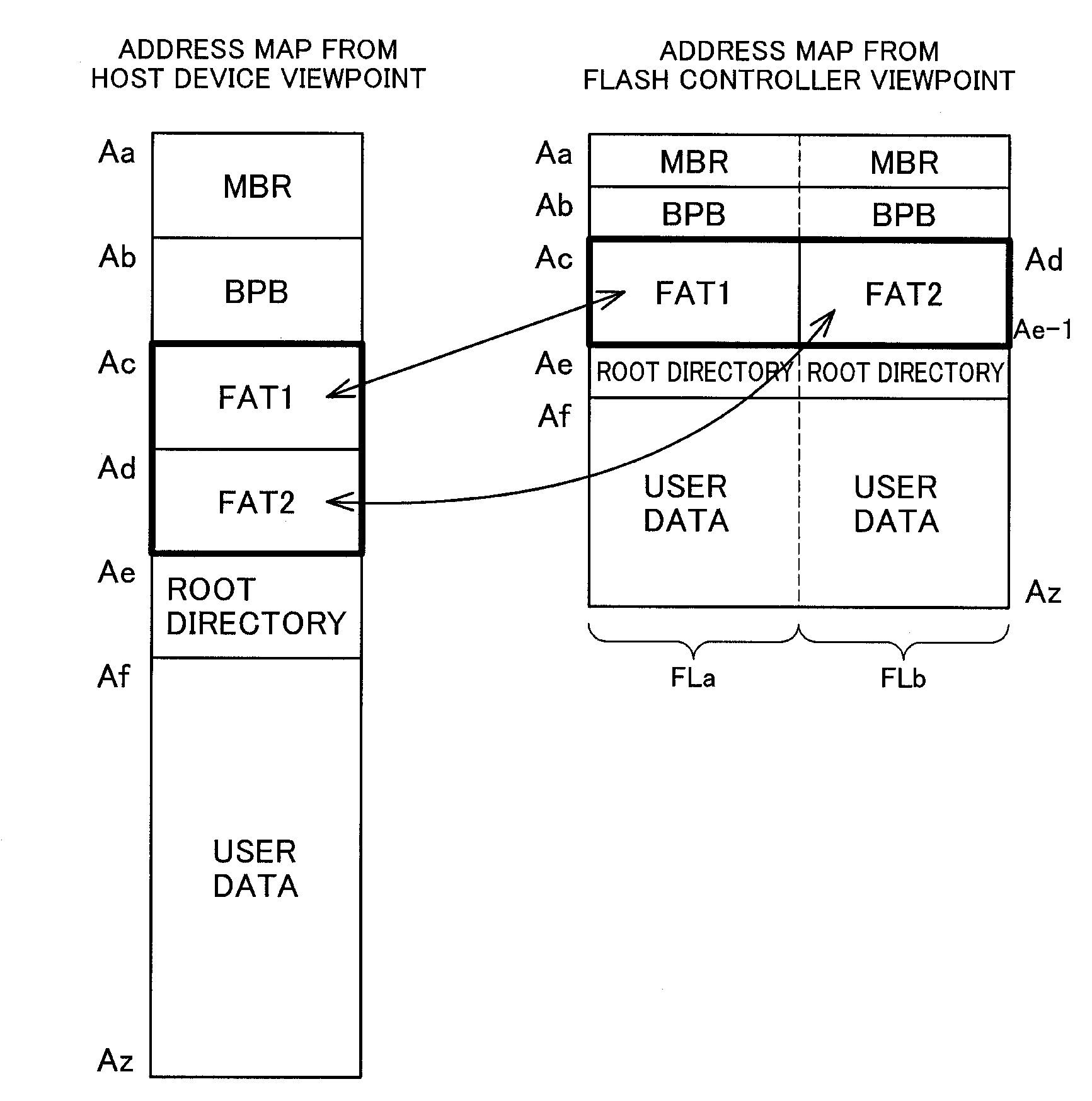
[0103]FIG. 10 is an explanatory view showing the data structure in the data storage apparatus 10b. The left drawing of FIG. 10 shows an address map of the data storage apparatus 10b from the viewpoint of the host device. This address map is identical with the address map explained in the first embodiment and is thus not specifically described here.
[0104]The right drawing of FIG. 10 ...
third embodiment
C. Third Embodiment
[0107]The data structure of the second embodiment causes the data with regard to the area other than the FAT area to be written in a distributive manner in the two flash memories. A data structure of a third embodiment, on the other hand, causes data of identical content with regard to the area other than the FAT area to be written in two flash memories. A data storage apparatus 10b of the third embodiment has the same configuration as that of the data storage apparatus 10b of the second embodiment shown in FIG. 9.
[0108]FIG. 11 is an explanatory view showing the data structure in the data storage apparatus 10b of the third embodiment. The left drawing of FIG. 11 shows an address map of the data storage apparatus 10b from the viewpoint of the host device. The right drawing of FIG. 11 shows an address map of the two flash memories FLa and FLb. In the data structure of the third embodiment, with regard to the areas other than the FAT areas, that is, the MBR area, the...
PUM
 Abstract
Description
Claims
Application Information
 - R&D Engineer
- R&D Manager
- IP Professional
- Industry Leading Data Capabilities
- Powerful AI technology
- Patent DNA Extraction
Browse by: Latest US Patents, China's latest patents, Technical Efficacy Thesaurus, Application Domain, Technology Topic.
© 2024 PatSnap. All rights reserved.Legal|Privacy policy|Modern Slavery Act Transparency Statement|Sitemap