
Supporting structure for adjustable air guide vanes

a technology of air guide vane and support structure, which is applied in the direction of ventilation system, heating type, lighting and heating apparatus, etc., can solve the problems of unstable rotational movement of the vane, poor operational feeling of the operation knob, and unstable operational feeling of the vane, so as to achieve stable load resistance to rotation and good operational feeling of the rotation of the air guide vane

Inactive Publication Date: 2009-05-28
MORIROKU TECH
View PDF1 Cites 16 Cited by
  • Summary
  • Abstract
  • Description
  • Claims
  • Application Information

AI Technical Summary

Benefits of technology

[0005]The objective of the present invention is to provide a structure for supporting air guide vanes in a supply opening for air conditioning, which can produce a stable load resistance to rotation of the air guide vane when rotating the air guide vane, so that a good operational feeling of rotation of the air guide vane can be obtained.
[0006]Another objective of the present invention is to provide a structure for supporting an air guide vane in a supply opening for air conditioning, which can prevent causing abrupt changes in the load resistance to rotation of the air guide vane, so that a good operational feeling of rotation of the air guide vane can be obtained.
[0007]Further objective of the present invention is to provide a structure for supporting an air guide vane in a supply opening for air conditioning, which can maintain a virtually constant operational feeling of rotation of the air guide vane even if the rotation of the air guide vane is repeated.

Problems solved by technology

Therefore, the operational feeling of the operation knob is affected not only by the slidability of the operation knob but also by the rotational friction force of the louvers or vanes.
Consequently, if the rotation shaft of a vane is borne by the molded part having the aforementioned rough surface, the operational feeling of the vane becomes worse and the rotational movement of the vane becomes unstable.
In addition, the molded part for supporting the vane tends to suffer wear or uneven abrasion due to repeated rotation of the vane.
Since a required torque to rotate the vane varies as the molded part is worn away, it becomes more difficult to retain the predetermined operational feeling of the vane for a long period of time.

Method used


Image

  • Supporting structure for adjustable air guide vanes
  • Supporting structure for adjustable air guide vanes
  • Supporting structure for adjustable air guide vanes

Examples


Embodiment Construction

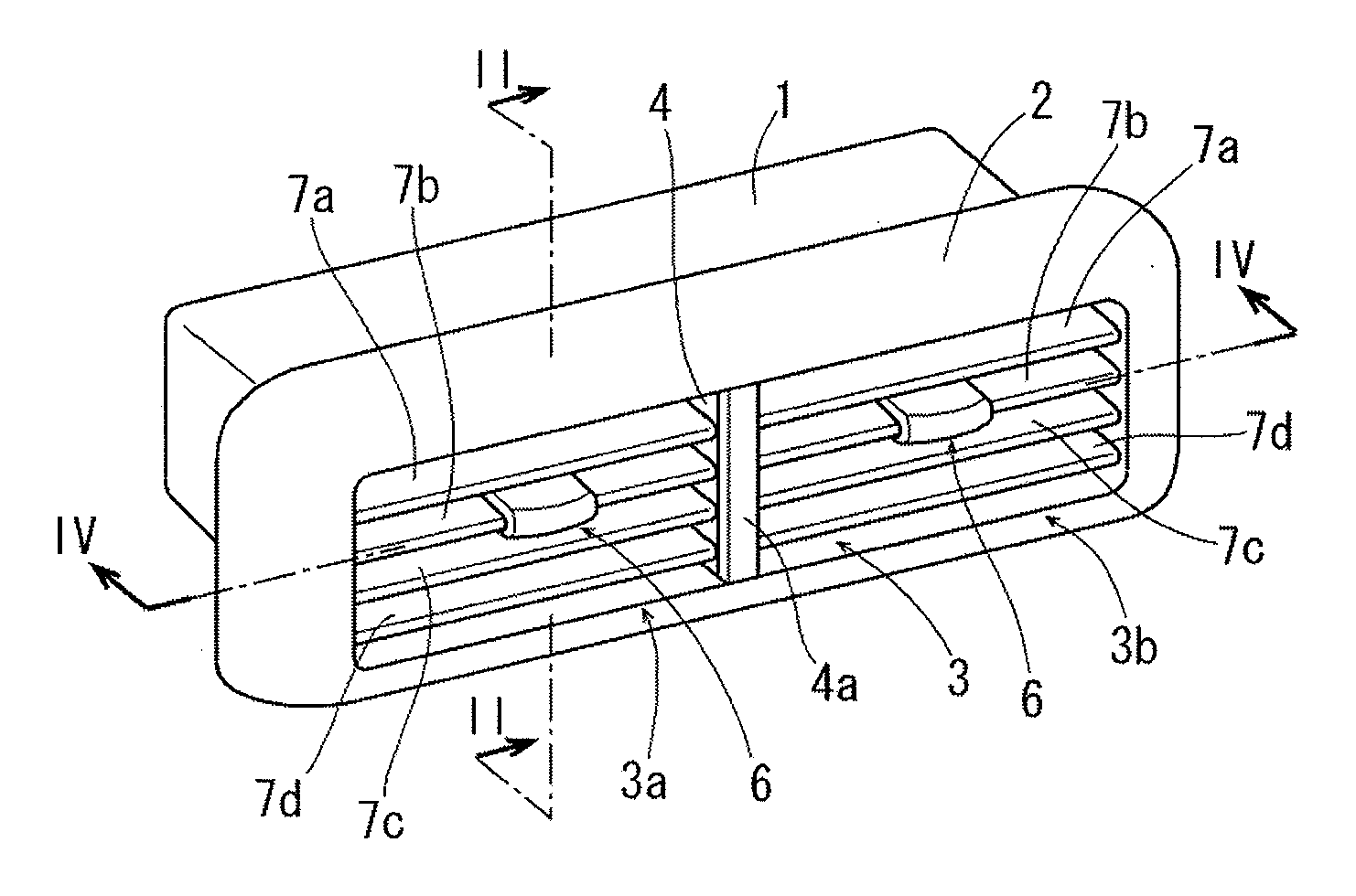
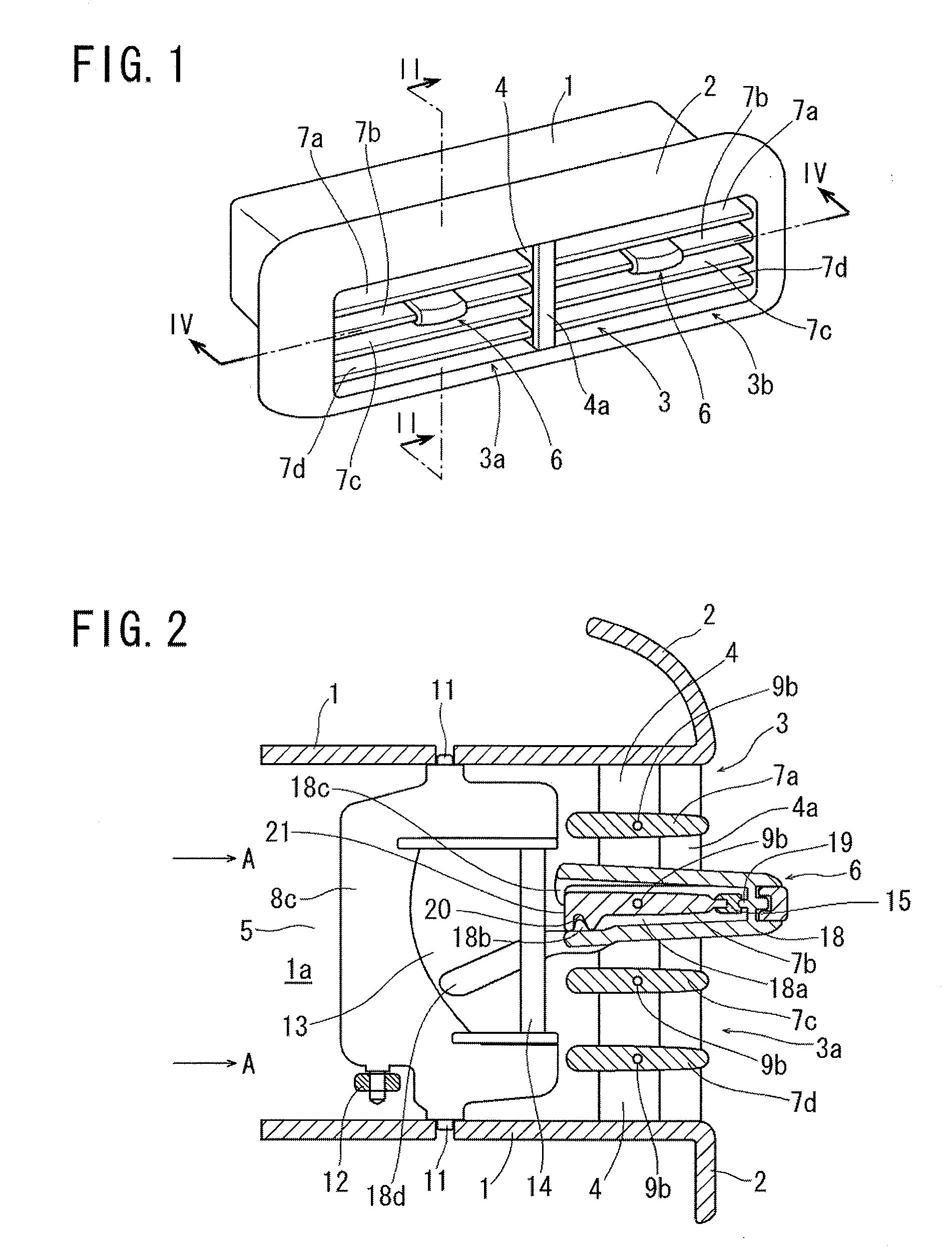
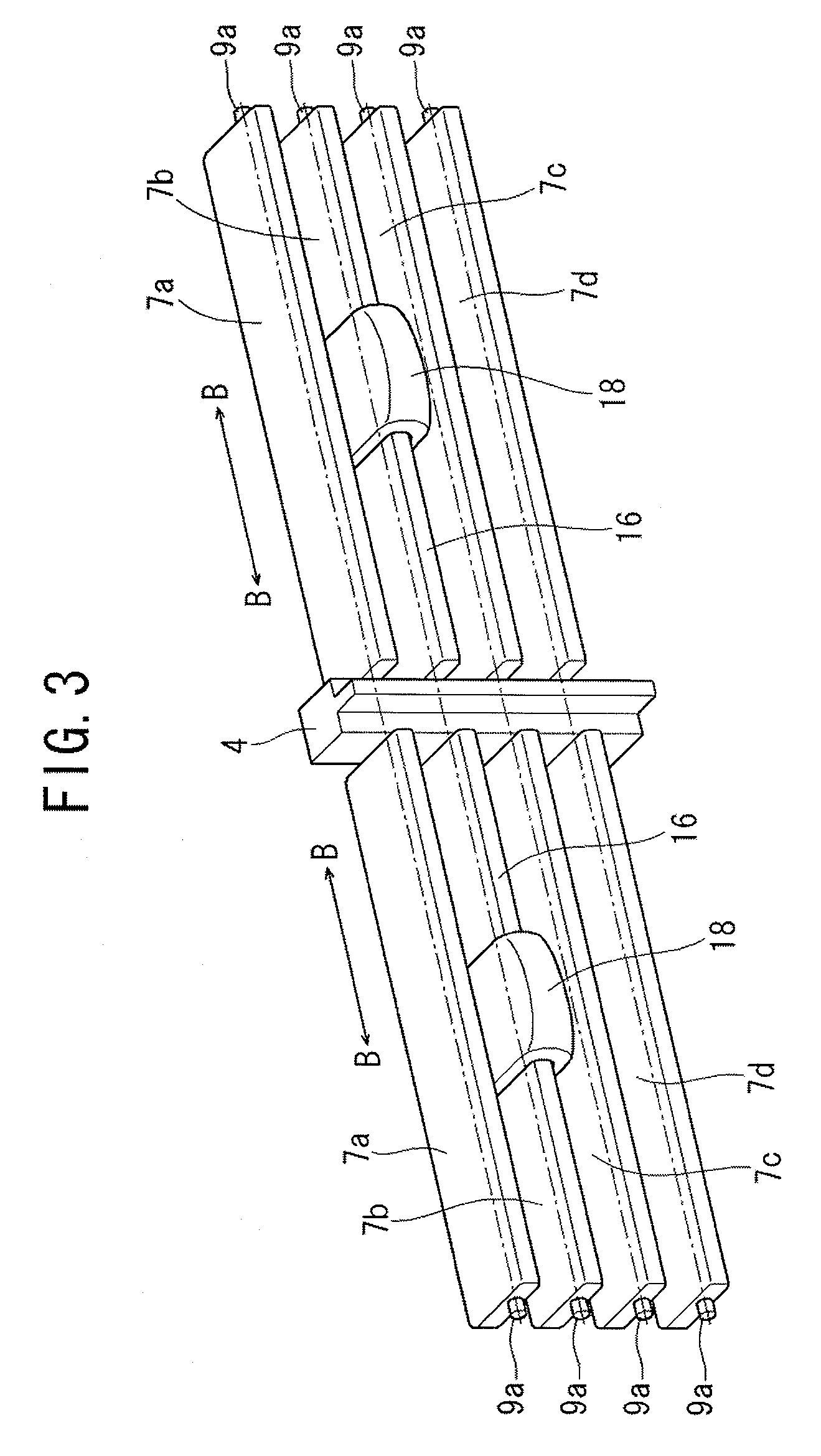
[0032]FIGS. 1-6 illustrate an embodiment of the present invention wherein the supporting structure for adjustable air guide vanes according to the present invention is embodied in an apparatus for changing the direction of airflow, which is disposed in a supply opening for air conditioning, and the supply opening opens into a vehicle interior. An opening 3 is formed in a panel portion 2 defined at the end of an air-conditioning duct 1 and a supporting member 4 is attached to the central portion of the opening 3. A cover member 4a is fitted on the front surface of the supporting member 4 and by the supporting member 4 and the cover member 4a, the opening 3 is divided into two supply openings 3a, 3b for air conditioning. As illustrated in FIGS. 2 and 5, the supporting member 4 is connected to a partition wall 5 by which two passages 1a, 1b are defined in the air-conditioning duct 1. The supply opening 3a is communicated with the passage 1a, while the supply opening 3b is communicated ...


PUM


Abstract

A structure for supporting an air guide vane in a supply opening for air conditioning prevents abrupt changes of load resistance to rotation of the air guide van and provides a good operational feel when rotating the air guide vane. A supporting member of the air guide vane is an olefin-based thermoplastic elastomer having a hardness of between Shore A80 and Shore D60. The degree of mold transferability of olefin-based thermoplastic elastomer is characteristically lower than that of other thermoplastic elastomers. By virtue of molding an olefin-based thermoplastic elastomer microscopic concavities and convexities are formed on the surface of the supporting member. The rotation shaft of the air guide vane is supported by multiple point contacts with the inner surface respective through-holes.

Description

FIELD OF THE INVENTION[0001]The present invention relates to a structure for supporting an air guide vane in a supply opening for air conditioning in vehicles, especially relates to a structure for supporting an adjustable air guide vane.DESCRIPTION OF THE RELATED ART[0002]An apparatus for changing the direction of airflow from a supply opening for air conditioning, which comprises a plurality of vanes for changing the direction of airflow from an air-conditioning duct and a manual operation knob handled by a vehicle driver to change the direction of the vanes, has been suggested in the past. For example, Japanese Patent Public Disclosure No. H10-250357 discloses a wind direction adjusting device that is designed to prevent deterioration of an outside appearance due to use of an operation knob, and to make it possible to reduce the control force for sliding the operation knob, and the rest.[0003]In such an apparatus, wind direction is adjusted by a vehicle driver who manually operat...

Claims


Application Information

Patent Timeline
Patent Type & Authority Applications(United States)
IPC IPC(8): F24F7/00
CPCB60H1/3421B60H2001/3471B60H2001/3464
Inventor FUJIWARA, YUJI
Owner MORIROKU TECH
Learn More