
Ultrasonic imaging apparatus and ultrasonic imaging method

a technology of ultrasonic imaging and ultrasonic imaging, applied in tomography, instruments, applications, etc., can solve the problem of inevitability of image quality decline, and achieve the effect of high image quality

Active Publication Date: 2009-05-28
GE MEDICAL SYST GLOBAL TECH CO LLC
View PDF12 Cites 26 Cited by
  • Summary
  • Abstract
  • Description
  • Claims
  • Application Information

AI Technical Summary

Benefits of technology

[0028]In the first aspect, the ultrasonic imaging apparatus that captures a plurality of B-mode images of a same cross section respectively by a plurality of linear scans with different directional ultrasonic beams and creates and displays a compound image from the plurality of B-mode images includes a device for capturing an image to capture a plurality of B-mode images respectively by a linear scan with an ultrasonic beam steered to a reference direction and a linear scan or scans with an ultrasonic beam or beams steered to one or more directions different from the reference direction; a device for creating an image to create a compound image using the plurality of B-mode images; and a display device to display the compound image. Therefore, it is possible to realize an ultrasonic imaging apparatus that satisfies both requirements of a proper FOV and a high image quality.
[0032]In the fifth aspect, the ultrasonic imaging apparatus that captures a plurality of B-mode images of a same cross section by a plurality of linear scans with different directional ultrasonic beams respectively and creates and displays a compound image from the plurality of B-mode images includes a device for capturing a right oblique image to capture a plurality of B-mode images respectively by a linear scan with an ultrasonic beam oriented at a reference direction that is angled to the right and a linear scan or scans with an ultrasonic beam or beams steered to one or more directions different from the reference direction; a device for capturing an image at a right angle to the front to capture a plurality of B-mode images respectively by a linear scan with an ultrasonic beam oriented at a reference direction that is square to the front and a linear scan or scans with an ultrasonic beam or beams steered to one or more directions different from the reference direction; a device for capturing a left oblique image to capture a plurality of B-mode images respectively by a linear scan with an ultrasonic beam oriented at a reference direction that is angled to the left and a linear scan or scans with an ultrasonic beam or beams steered to one or more directions different from the reference direction; a device for creating a first compound image to create a first compound image using the plurality of B-mode images captured by the device for capturing a right oblique image; a device for creating a second compound image to create a second compound image using the plurality of B-mode images captured by the device for capturing an image at a right angle to the front; a device for creating a third compound image to create a third compound image using the plurality of B-mode images captured by the device for capturing a left oblique image; a device for creating an expanded image to create an expanded compound image by combining any two or all of the first compound image, the second compound image, and the third compound image; and a display device to display the expanded compound image. Therefore, it is possible to realize an ultrasonic imaging apparatus that satisfies both requirements of a proper FOV and a high image quality.
[0037]In the tenth aspect, the display device displays an icon for the FOV; therefore, FOV shape can be recognized easily.

Problems solved by technology

In these scans, however, because the density of acoustic lines decreases in a far field, a decrease in the image quality is inevitable.

Method used


Image

  • Ultrasonic imaging apparatus and ultrasonic imaging method
  • Ultrasonic imaging apparatus and ultrasonic imaging method
  • Ultrasonic imaging apparatus and ultrasonic imaging method

Examples


Embodiment Construction

[0048]In the following, various embodiments of the invention will be described in detail with reference to the drawings. It should be understood that the invention is not limited to embodiments described herein.

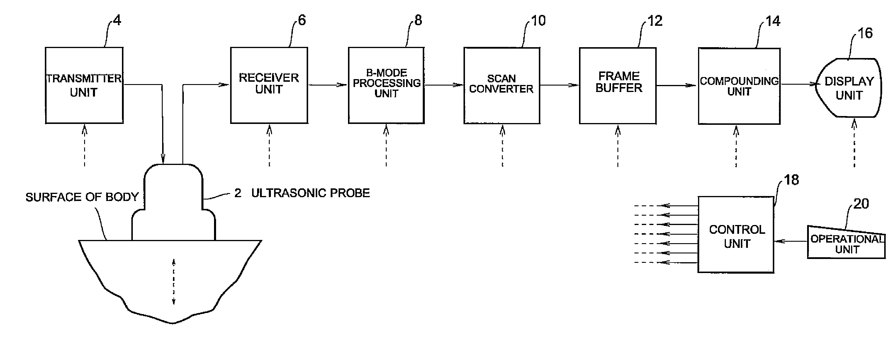
[0049]A block of an exemplary ultrasonic imaging apparatus is shown in FIG. 1.

[0050]As shown in FIG. 1, the apparatus includes an ultrasonic probe 2. The ultrasonic probe 2 has an ultrasonic transducer array. In the ultrasonic transducer array, each individual ultrasonic transducer is made of piezoelectric material such as, for example, PZT (lead (Pb) zirconate (Zr) titanate (Ti)), ceramics, etc.

[0051]The ultrasonic probe 2 is used in touch with the surface of the body. To the ultrasonic probe 2, a transmitter unit 4 and a receiver unit 6 are connected. The transmitter unit 4 outputs a signal to drive the ultrasonic probe 2, thereby causing the ultrasonic probe 2 to perform scanning with an ultrasonic beam. The receiver unit 6 performs amplification and received beam forming ...


PUM


Abstract

An ultrasonic imaging apparatus captures a plurality of B-mode images of a same cross section respectively by a plurality of linear scans with different directional ultrasonic beams and creates and displays a compound image from the plurality of B-mode images. The ultrasonic imaging apparatus includes a device for capturing an image to capture a plurality of B-mode images respectively by a linear scan with an ultrasonic beam steered to a reference direction and a linear scan or scans with an ultrasonic beam or beams steered to one or more directions different from the reference direction, a device for creating an image to create a compound image using the plurality of B-mode images, and a display device to display the compound image.

Description

CROSS REFERENCE TO RELATED APPLICATIONS[0001]This application claims the benefit of Chinese Patent Application No. 200710305161.1 filed Nov. 22, 2007, which is hereby incorporated by reference in its entirety.BACKGROUND OF THE INVENTION[0002]The subject matter disclosed herein relates to an ultrasonic imaging apparatus and, particularly, relates to an ultrasonic imaging apparatus that captures a plurality of B-mode images of a same cross section respectively by a plurality of linear scans with different directional ultrasonic beams and creates and displays a compound image from these B-mode images.[0003]An ultrasonic imaging apparatus scans a range to be imaged with an ultrasonic beam, generates a B-mode image from echo signals received, and displays the image. Some ultrasonic imaging apparatus captures a plurality of B-mode images of a same cross section by a plurality of linear scans with different directional ultrasonic beams respectively and creates and displays a compound image...

Claims


Application Information

Patent Timeline
IPC IPC(8): A61B8/14
CPCA61B8/14A61B8/0841G01S15/8995A61B8/463
Inventor WU, FANGGANGCHEN, HUIRENXI, SHUI
Owner GE MEDICAL SYST GLOBAL TECH CO LLC
Learn More