Syringe

a syringe and syringe technology, applied in the field of syringes, can solve the problems of long use time, and achieve the effect of ensuring easy and safe operation of the syring

Inactive Publication Date: 2009-05-28
HENKE SASS WOLF
View PDF5 Cites 60 Cited by
  • Summary
  • Abstract
  • Description
  • Claims
  • Application Information

AI Technical Summary

Benefits of technology

[0006]In view thereof, it is an object of the invention to improve a syringe of the above-mentioned type such that easy and safe operation of the syringe can be ensured.

Problems solved by technology

Such a re-usable syringe can be used for a very long time.

Method used


Image

  • Syringe
  • Syringe
  • Syringe

Examples


Embodiment Construction

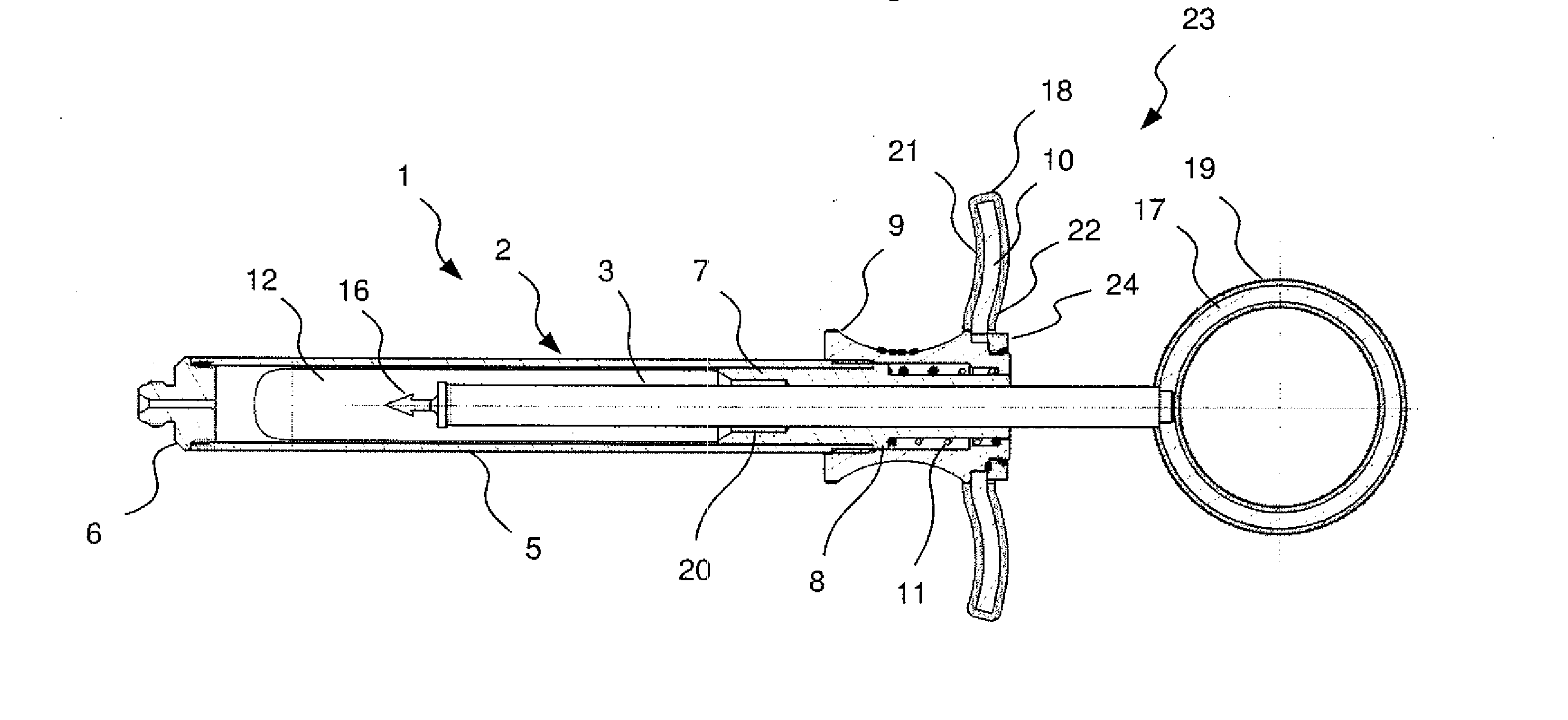
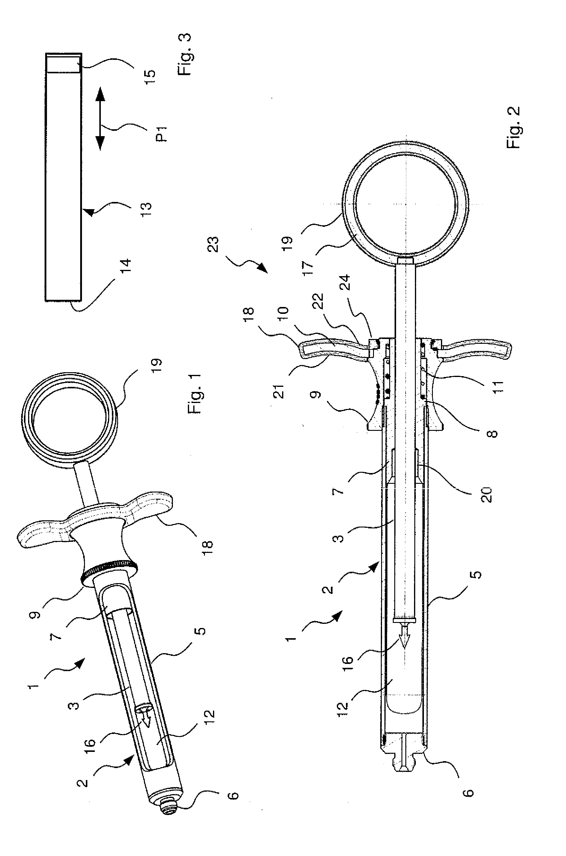
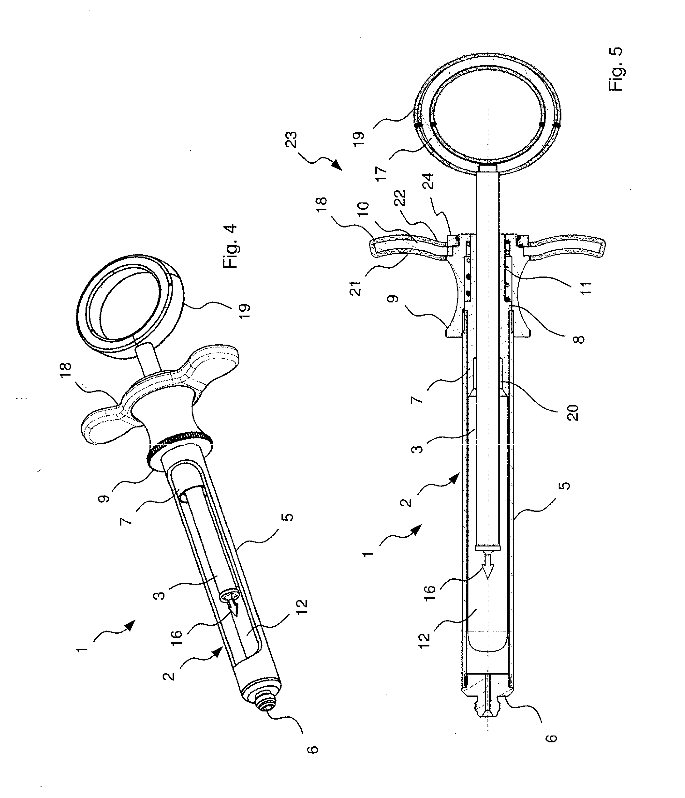
[0028]In the embodiments shown in FIGS. 1 and 2, the syringe 1 according to the invention is provided as a carpule syringe, which may also be referred to as a cylindrical-ampoule syringe. The syringe 1 comprises a substantially tubular syringe body 2, in which a plunger rod 3 is supported in a longitudinally displaceable manner.

[0029]The syringe body 2 comprises a hollow-cylinder main tube 5 comprising a needle port 6 at the front end and a centering sleeve 7 inserted at the rear end. The needle port 6 is screwed into and glued to the main tube 5. The centering sleeve 7 is inserted into the main tube 5 as far as the stop 8 of the centering sleeve 7, which stop 8 abuts against the rear end of the main tube 5. Further, the rear end of the main tube 5 has a grip cap 9 screwed on and glued to it, and a finger support 10 is rotatably mounted on the rear end of the grip cap 9 and secured by a ring 24. For this purpose, the ring 24 is screwed on and glued to the rear end of the finger supp...


PUM


Abstract

A syringe is provided, comprising a syringe body, a plunger rod, which is guided in the syringe body in a longitudinally displaceable manner, and a grip area which includes a finger portion formed on the syringe body and a thumb portion formed at the rear end of the plunger rod, the grip area being at least partially provided with a friction coating which consists of a different material than the grip area.

Description

PRIORITY APPLICATION[0001]The current application claims the benefit of priority to German Patent Application No. DE 10 2007 056 240.5 filed on Nov. 22, 2007. Said application is incorporated in its entirety by reference herein.BACKGROUND OF THE INVENTION[0002]1. Field of the Invention[0003]The present invention relates to a syringe comprising a syringe body, a plunger rod, which is guided in the syringe body in a longitudinally displaceable manner, and a grip area which includes a finger portion formed on the syringe body and a thumb portion formed at the rear end of the plunger rod.[0004]2. Background[0005]In many cases, such syringes, if they are re-usable syringes, are made from metal. The metal surface is usually as smooth as possible to allow good sterilization or autoclaving of the syringe. However, this leads to the difficulty that it is relatively easy for the fingers to slip off the finger portion or for the thumb to slip off the thumb portion during operation of the syrin...

Claims


Application Information

Patent Timeline
Patent Type & Authority Applications(United States)
IPC IPC(8): A61M5/315
CPCA61M5/24A61M5/3135A61M5/3137A61M2205/6081A61M5/31515A61M2005/3139A61M2205/586A61M5/3148
Inventor RUECKERT, RALFKNEFEL, STEFAN
Owner HENKE SASS WOLF
Why Eureka
Try Eureka