Wire cable reinforced carrying strap

a technology of reinforcing cables and straps, which is applied in the field of carrying straps, can solve the problems of increasing the number of separate manufacturing steps required, increasing the component of labour costs of straps of this type, and kinking of wires, so as to avoid permanent deformation of reinforcing cables and the effect of avoiding the deformation of wires

Inactive Publication Date: 2009-06-04
MRM HK
View PDF10 Cites 43 Cited by
  • Summary
  • Abstract
  • Description
  • Claims
  • Application Information

AI Technical Summary

Benefits of technology

[0021]The fitting provides in one component, both a large convex surface about which the doubled over portion of the strap is passed and an opening through wh

Problems solved by technology

It will be understood that although this prior art design also allows the straps to be readily manufactured using conventional sewing techniques, the number of separate manufacturing steps required tends to increase the component of labour costs in straps of this type.
However, a drawback of this prior art strap construction is that if, due to load on the strap, the loop is collapsed to a small diameter then the wires may be permanently deformed, providing a kink in the wire which makes further adjustment difficult.
Another dis

Method used


Image

  • Wire cable reinforced carrying strap
  • Wire cable reinforced carrying strap
  • Wire cable reinforced carrying strap

Examples


Embodiment Construction

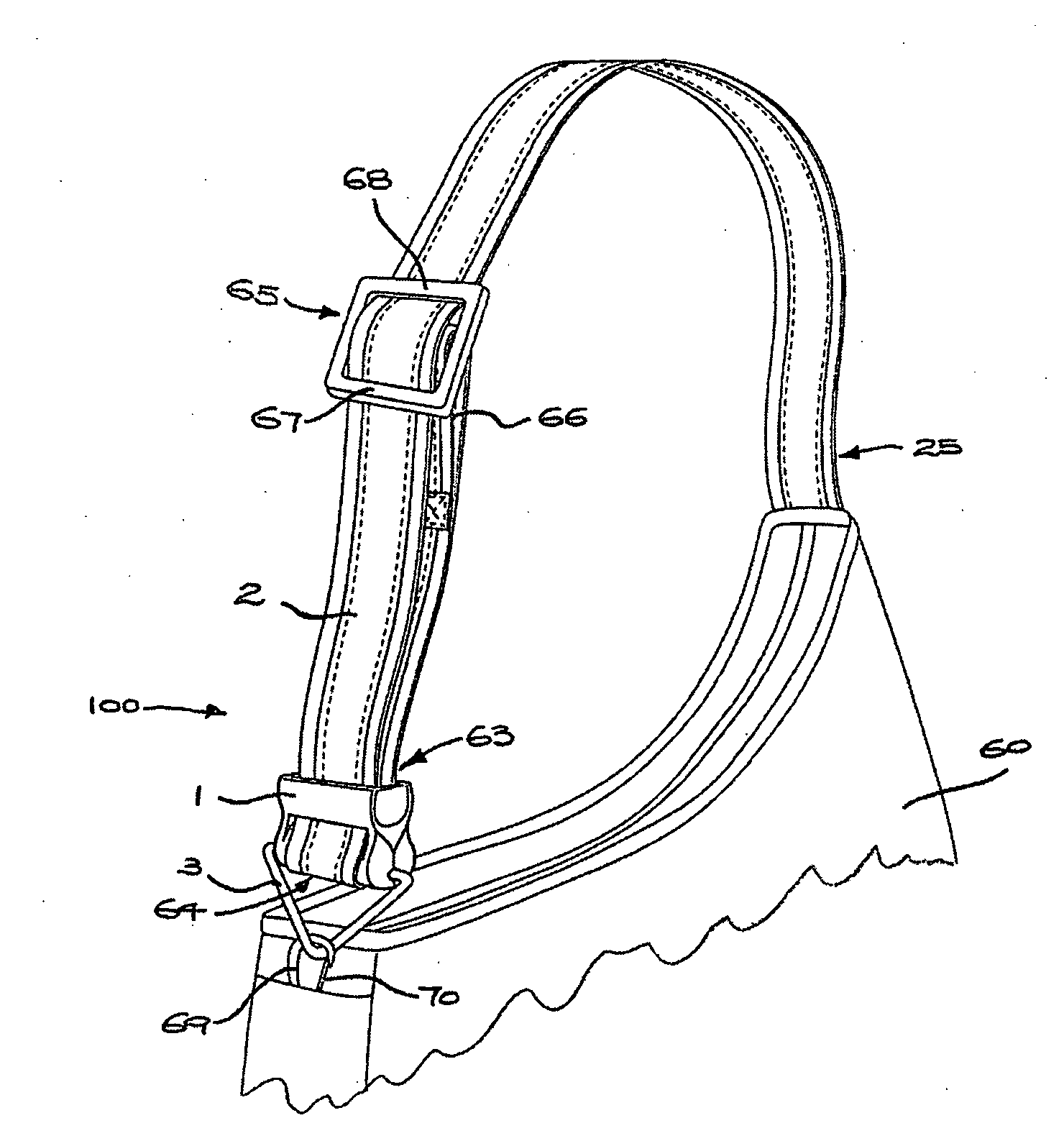
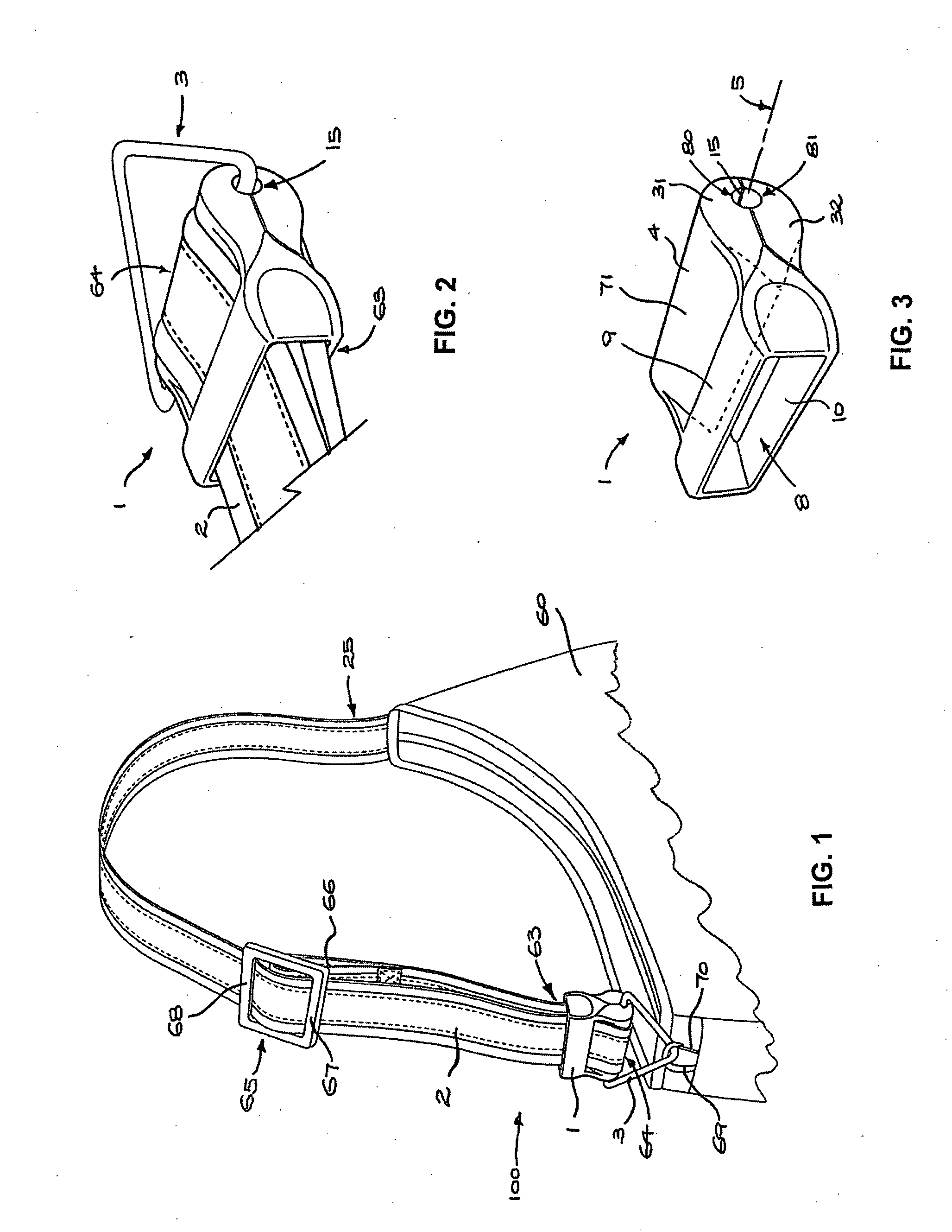
[0030]Referring to FIGS. 1 and 5, a bag 60 includes a carrying strap or shoulder strap assembly 100. The carrying strap assembly 100 includes a fitting 1, an elongate strap 2 and a ring 3. A length-adjustment buckle 65 has a central cross bar (not shown) and two end bars 67, 68. The strap 2 passes under the end bars 67, 68 and over the central bar before it passes through the fitting 1 and a length of the strap is doubled over upon itself to form a neck 63 that extends to a loop 64. The longitudinal end of the strap 2 is then fixed in a loop 66 around the cross bar. A transverse aperture 15 in the fitting 1 receives the ring 3. A fastener in the form of hook 69 fixed to the bag 60 releasably fastens the ring 3 to the bag 60. A spring keeper 70 is fixed to the hook 69 to avoid unintentional disconnection. Thus one end of the strap assembly 100 is connected to the bag 60, via the hook 69, while the other end 25 is fixed, as by a seam (not shown), directly to the bag 60.

[0031]The fitti...


PUM


Abstract

An elongate carrying strap reinforced by longitudinally extending multi-strand wire cables (41) is engaged with a fitting (1) for forming a loop (64) at an end of the strap (2) so as to avoid inelastic deformation of the cable. A pair of multi-strand wire cables are received in parallel envelopes (43) disposed on opposite longitudinal edges of the strap, each envelope is tubular and formed in a flexible polymer strip (40) extruded over the cable. The fitting has a transverse bar portion (71) having a convex face abutting the inner side of the loop and a pair of transverse arm portions (9, 10) defining an opening therebetween, the opening receiving a neck (63) of the loop and having opposing strap-engaging surfaces abutting the outer side of the strap and cooperating to hold the inner side against the convex face (4) of the bar portion (71).

Description

TECHNICAL FIELD[0001]The present invention relates to a carrying strap for a bag, or other item, attached in such manner that it forms a loop, the carrying strap being reinforced by wire cable for security.BACKGROUND OF THE INVENTION [0002]The use of steel wire cable reinforcement in the construction of flexible carrying straps for baggage provides an increased level of security against theft, particularly that achieved by slicing the strap. A prior art design employs two elongate wire cables to reinforce carrying straps of this type, the wire cables running longitudinally and received in fabric sleeves, formed by folding and sewing one or more panels, with the sleeves extending along opposing edges of the strap. Enveloping the wires within separate elongate apertures in this way keeps the wires separated, helping the strap lie flat in use and avoiding one wire overlying another in a manner which may cause discomfort. It will be understood that although this prior art design also al...

Claims


Application Information

Patent Timeline
IPC IPC(8): A45F3/14
CPCA45C13/30A45C13/18
Inventor SCHLIPPER, ROBERT WESLEY
Owner MRM HK
Why Eureka
Try Eureka