Multi-piece socket contact assembly

a socket and socket body technology, applied in the direction of coupling contact members, coupling device connections, electrical devices, etc., can solve the problem of a greater frictional engagement between the spring and the socket body, and achieve the effect of preventing (or reducing) the movement of the spring body

Active Publication Date: 2014-10-07
DEUT ENGINEERED CONNECTING DEVICES
View PDF14 Cites 18 Cited by
  • Summary
  • Abstract
  • Description
  • Claims
  • Application Information

AI Technical Summary

Benefits of technology

[0008]The present invention provides a multi-piece socket contact assembly that functions to secure a spring body against a socket body, thereby preventing (or reducing) movement of the spring body during a period of vibration. Preferred embodiments of the present invention operate in accordance with an assembly that includes a socket body, a spring body, and a sleeve.
[0010]In one embodiment of the present invention, the assembly further includes a spring body that is formed out of a second material, and preferably out of a single piece of the second material. While the second material can be any conductive material, it is preferably one that is different than the first material and has a high yield strength to avoid permanent deformation when deflected. In one embodiment of the present invention, the spring body includes a distal end and a proximal end, wherein the distal end includes a plurality of tines, and the proximal end includes a female connector (e.g., a plurality of fingers, etc.) that is configured to receive a male connector (e.g., a male pin, etc.). In a preferred embodiment of the present invention, the tines are configured to be placed over the proximal end of the socket body. Thus, for example, the tines may form at least one inner circumference that is either slightly larger than an outer circumference of the proximal end of the socket body, or slightly smaller than an outer circumference of the proximal end of the socket body. In the prior, the tines can be pressed over the proximal end of the socket body with a lesser amount of force, resulting in a lesser amount of frictional engagement between the spring and socket bodies. In the latter, the tines can be pressed over the proximal end of the socket body with a greater amount of force (e.g., as necessary to flex the tines in an outward direction), resulting in a greater amount of frictional engagement between the spring and socket bodies.
[0011]In one embodiment of the present invention, the assembly further includes a sleeve that includes at least one inner circumference that is sized to secure the spring body against the socket body. For example, the inner circumference of the sleeve may be equal to or slightly larger than the sum of the outer circumference of the proximal end of the socket body and the thickness of two opposing tines. In a preferred embodiment, the sleeve is pressed over the distal end of the spring body, thereby creating a frictional engagement between an inner surface of the sleeve and at least one outer surface of the distal end of the spring body, and between at least one inner surface of the distal end of the spring body and an outer surface of the proximal end of the socket body. By sandwiching (or compressing) the spring body between the sleeve and the socket body, a frictional force (or engagement) can be created that prevents (or at least reduces) movement of the spring body in relation to the socket body during periods of vibration.

Problems solved by technology

In the latter, the tines can be pressed over the proximal end of the socket body with a greater amount of force (e.g., as necessary to flex the tines in an outward direction), resulting in a greater amount of frictional engagement between the spring and socket bodies.

Method used


Image

  • Multi-piece socket contact assembly
  • Multi-piece socket contact assembly
  • Multi-piece socket contact assembly

Examples


Embodiment Construction

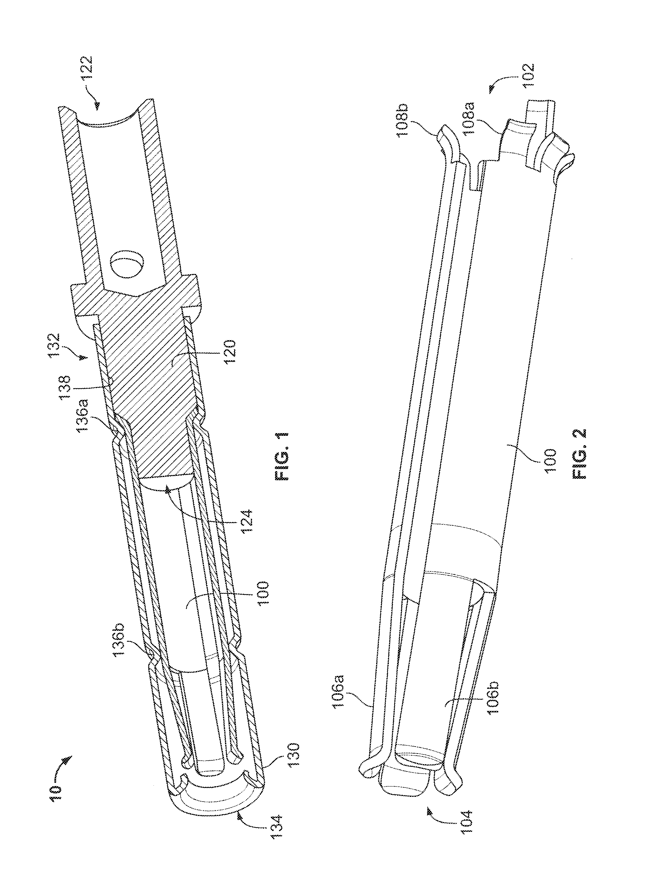
[0024]The present invention provides a multi-piece socket contact assembly that functions to reduce movement of a spring body in relation to a socket body during Periods of vibration. In the detailed description that follows, like element numerals are used to describe like elements illustrated in one or more figures.

[0025]A socket contact assembly in accordance with one embodiment of the present invention is shown in FIG. 1. Specifically, the assembly 10 includes a socket body 120 that is formed out of a first material, and preferably out of a single piece of the first material. While the first material can be any conductive material, it is preferably one that is very ductile, and allow permanent deformation without cracking (e.g., brass, leaded nickel copper, gold, etc.). In one embodiment of the present invention, the socket body includes a distal end 122 and a proximal end 124, wherein the proximal end is solid and has a substantially circular outer surface, and the distal end 12...


PUM

PropertyMeasurementUnit
circumferenceaaaaaaaaaa
angleaaaaaaaaaa
modulus of elasticityaaaaaaaaaa

Abstract

A system and method is provided for securing a spring body against a socket body, thereby reducing movement of the spring body during periods of vibration. Preferred embodiments of the present invention operate in accordance with a socket body that includes at least a proximal end, a spring body that includes at least a distal end, and a sleeve. In one embodiment of the present invention, the distal end of the spring body is configured to be placed over the proximal end of the socket body, and the sleeve is configured to be placed over the distal end of the spring body. The sleeve preferably includes an inner circumference that is sized to creating a frictional engagement between an inner surface of the sleeve and an outer surface of the spring body, and between an inner surface of the spring body and an outer surface of the socket body.

Description

BACKGROUND OF THE INVENTION[0001]1. Field of the Invention[0002]The present invention relates to a socket contact assembly, or more particularly, to an assembly that includes a spring body formed out of a first material, a socket body formed out of a second material, and a sleeve configured to secure the spring body to the socket body, thereby at least reducing movement of the spring body in relation to the socket body during periods of vibration.[0003]2. Description of Related Art[0004]Connectors are used in many applications, including commercial, consumer and military applications. Connectors are typically used to transmit information (e.g., a voltage, current, etc.) from a first device to a second device. For example, a connector may be used to provide power from a power supply to a circuit. By way of another example, a connector may be used to provide analog and / or digital information from a first circuit to a second circuit.[0005]In order to ensure electrical continuity in a c...

Claims


Application Information

Patent Timeline
Patent Type & Authority Patents(United States)
IPC IPC(8): H01R13/187
CPCH01R13/111H01R13/187Y10T29/49217Y10T29/49208Y10T29/49218H01R13/11
Inventor FRIEDHOF, JAMES P.RENGIFO, ALEX ROBERTBIANCA, GIUSEPPE
Owner DEUT ENGINEERED CONNECTING DEVICES
Why Eureka
Try Eureka