Stent having struts with reverse direction curvature

a technology of struts and struts, which is applied in the field of stents, can solve the problems of permanent deformation of stents and inability to fully expand when deployed, and achieve the effects of increasing the expansion/compression ratio of stents, and reducing the risk of fractur

Active Publication Date: 2010-07-27
MEDINOL LTD
View PDF141 Cites 16 Cited by
  • Summary
  • Abstract
  • Description
  • Claims
  • Application Information

AI Technical Summary

Benefits of technology

[0008]The present invention provides a stent with an increased expansion to compression ratio compared to currently available stents. Specifically, a self-expandable stent of the present invention have an expansion / compression ratio of about 7:1, whereas conventional self-expandable stents typically have an expansion / compression ratio up to about 5:1. The increased expansion / compression ratio of the stents of the present invention may be achieved by decreasing the compressed diameter of the stent when it is compressed on or in the stent delivery system and / or increasing the expanded diameter of the stent when it is deployed.
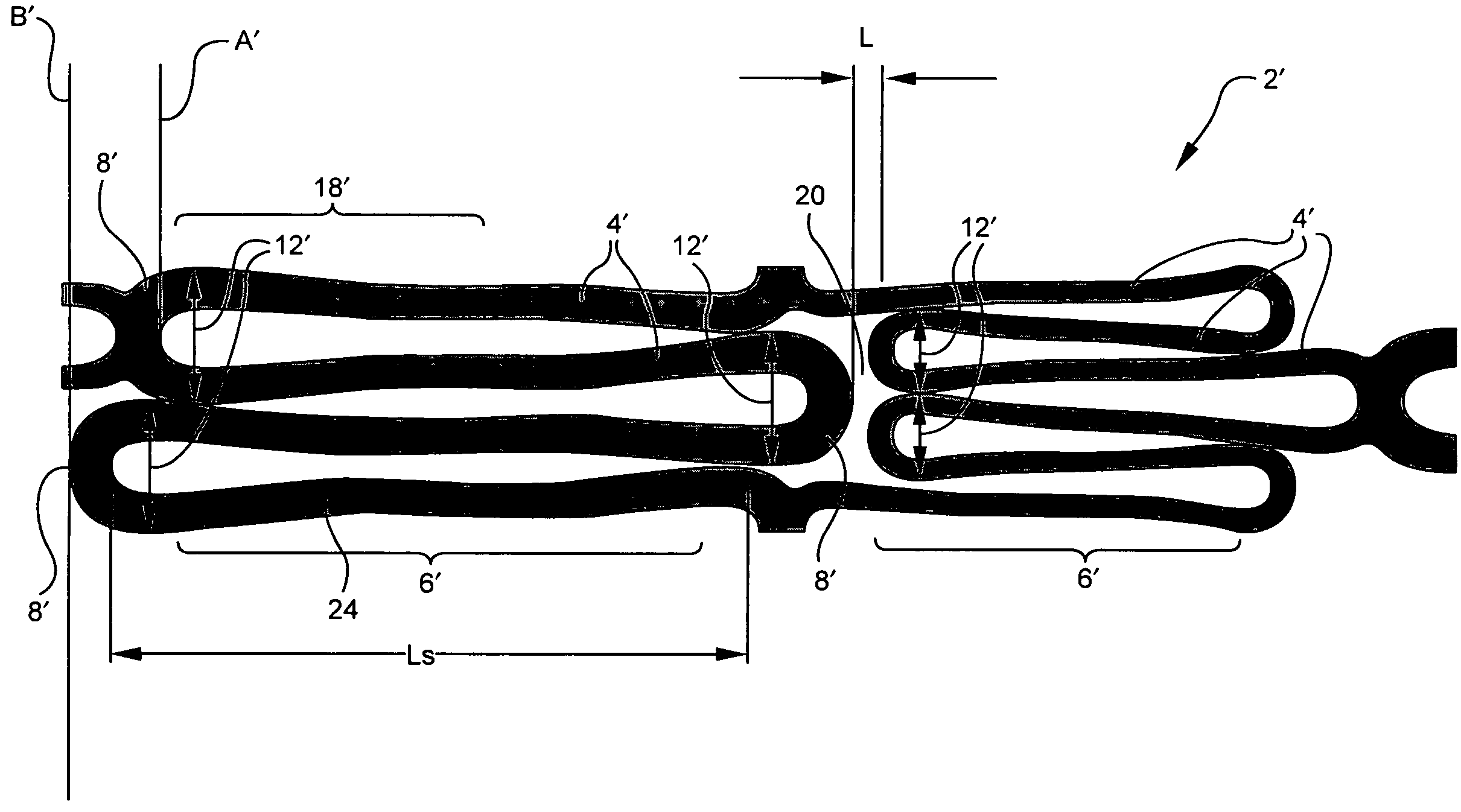
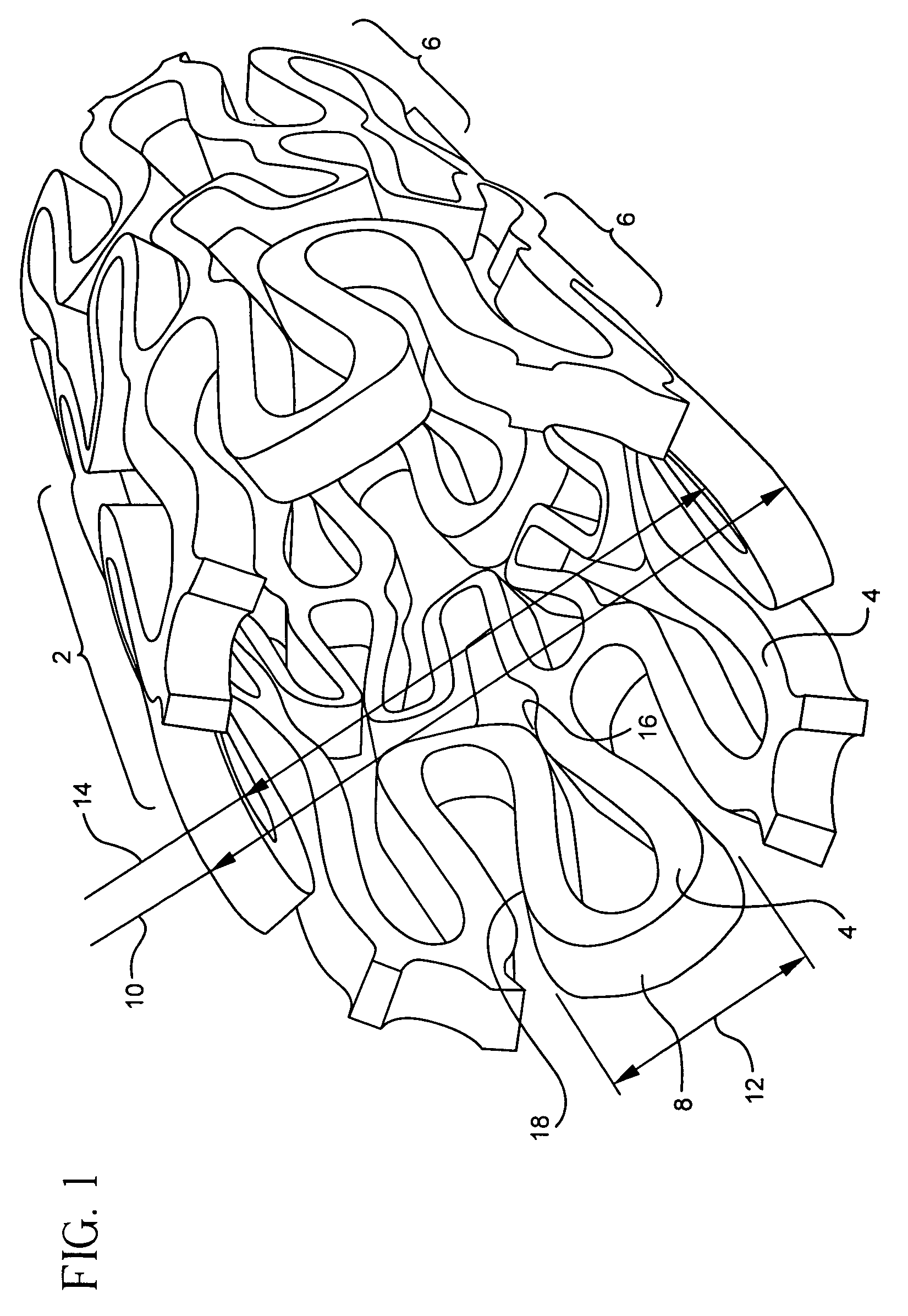
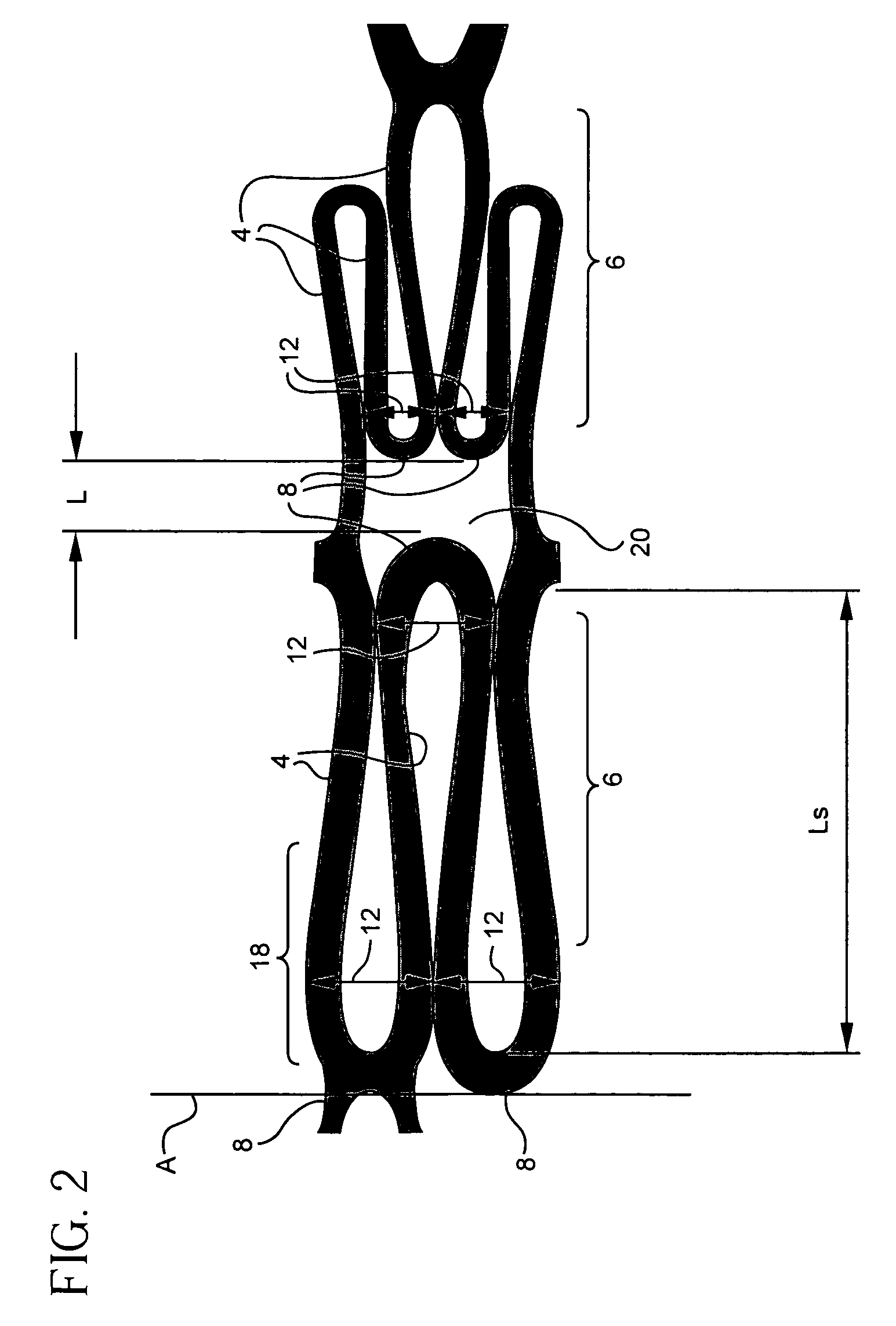
[0009]Stents of the present invention may be adapted to have a reduced compressed profile compared to conventional stents by utilizing struts with reverse direction curvature. Each strut has opposing arcuate curves or arches extending from each end to about its mid-section. These opposing curves join together at about the midsection of the strut, but are not necessarily limited to joining at this location. Each two adjacent struts in a circumferential section of the stent are joined at an end by a loop. When the stent is compressed, the struts straighten and extend. Due to this configuration, the largest circumferential width of each set of loop and adjoining struts of stent may be significantly reduced thereby reducing the overall compressed diameter of the stent.
[0010]Utilizing variable length struts within a circumferential section of the stent may further increase the expansion to compression ratio as shown in the various embodiments of the stent of the present invention. By varying the lengths of the struts in a circumferential section of the stent, the largest circumferential widths of adjacent sets of loops and adjoining struts may be offset. Accordingly, the largest circumferential widths of adjacent sets of loops and adjoining struts will not interfere with each other and impede the compression of the stent. In addition, increasing the lengths of some of the struts will enable the stent to have an increased expanded diameter when deployed.
[0011]The expansion to compression ratio may be further increased by a redistribution of the stress / strain forces imparted in the stent, preferably toward the strut sections, during stent compression to prevent permanent deformation of the stent or material failure. When compressed, conventional stents experience high concentrations of stress / strain in the loop sections of the stent. If the levels of stress / strain exceed the elastic limits (reversible strain) of the self-expanding stent, the stent will become permanently deformed and will not fully expand when deployed. The stress / strain imparted on the various embodiments of the present invention may be redistributed by varying the relative strength or flexibility of different portions of the stent. For example, the amount of material used to form different portions of the stent can be varied to change the portions' relative strength or flexibility. This variation can be accomplished by increasing the thickness or width of the loop portions to increase the strength of these portions relative to the strut portions. Preferably, the strut width is also gradually decreased from both ends towards the strut's midsection to further redistribute stress / strain forces away from the loop portions and toward the midsection of the strut portion of the stent.
[0012]The reverse direction curvature design of the strut of the present invention also increases the flexibility of the strut relative to that of the loop so that the stent can be further compressed without exceeding its elastic limit. Specifically, the junction in the midsection of the strut between opposing concave and convex curvatures in the strut has increased flexibility relative to the other portions of the strut and the loop. Accordingly, when the stent is compressed the compression forces are redistributed from the loop portions of the stent to the midsection of the strut portions.

Problems solved by technology

If the levels of stress / strain exceed the elastic limits (reversible strain) of the self-expanding stent, the stent will become permanently deformed and will not fully expand when deployed.

Method used


Image

  • Stent having struts with reverse direction curvature
  • Stent having struts with reverse direction curvature
  • Stent having struts with reverse direction curvature

Examples


Embodiment Construction

[0028]The present invention is preferably used with self-expanding stents, but is not limited to applications involving only self-expanding stents. The following detailed description will describe embodiments involving self-expanding stents, however, variations of the invention may be used with balloon-expandable stents and the like.

[0029]Self-expanding stents may be delivered to the deployment site using a delivery catheter system balloon catheter. The self-expanding stent is typically placed within a tube located at the distal end of the catheter that places physical limitations on the stent. The tube places physical limitations on the stent and retains the stent in its compressed state until it reaches the deployment site. It is desirable to compress the stent to its smallest possible diameter to minimize the profile of the delivery system. This minimized profile allows the delivery system to navigate the stent through narrow restrictions, where ultimately the stent is deployed a...


PUM


Abstract

Disclosed is a stent having struts with reverse direction curvature for providing a reduced compressed profile and an increased expanded profile. The strut configuration comprises a plurality of arcuate sections facing in opposite convex and a concave orientation. The strut width may be gradually decreased from its ends towards the strut's mid-section to redistribute maximal strains away from portions of the stent more susceptible to permanent deformation, such as the loop portions. Varying strut lengths to offset the maximum circumferential widths of adjacent portions of the stent may further reduce the compressed stent profile. The varied stent lengths may also contribute to an increased expanded stent profile. Stents with the reverse direction curvature strut design can obtain an expanded to compressed stent diameter ratio of about 7:1 compared to conventional stents that have a ratio of up to about 5:1. The curved strut can be utilized with any stent design.

Description

FIELD OF THE INVENTION[0001]The present invention relates generally to a structure for lumenal prostheses. More particularly, the present invention relates to a stent having a reduced compressed profile and an enlarged expanded profile.BACKGROUND[0002]Lumenal prostheses are used for a variety of medical purposes. Stents, for example, can be placed in various body lumens, such as a blood vessel, biliary tract and gastrointestinal tract, for maintaining patency.[0003]Stents placed in a blood vessel or a coronary artery are typically used to maintain the opening of the vessel wall. In order to do this, the stent must be deployed to the site within the vessel where support is needed, which can be accomplished in a variety of ways. In one common procedure, referred to as percutaneous transluminal coronary angioplasty (PTCA), a balloon catheter is used to open the vessel walls for creating a passageway. A stent is then placed in the newly opened passageway to prop open the vessel. An alte...

Claims


Application Information

Patent Timeline
Patent Type & Authority Patents(United States)
IPC IPC(8): A61F2/86A61F2/00A61F2/90
CPCA61F2/915A61F2002/91525A61F2230/0054A61F2002/91558A61F2250/0036A61F2002/91533
Inventor PINCHASIK, GREGORY
Owner MEDINOL LTD
Why Eureka
Try Eureka