Device for distributing gas to a cooking appliance

Inactive Publication Date: 2009-06-04
COPRECITEC
View PDF13 Cites 55 Cited by
  • Summary
  • Abstract
  • Description
  • Claims
  • Application Information

AI Technical Summary

Problems solved by technology

This device for gas distribution presents a problem in that the casing and the rotary plug member have substantially circul

Method used


Image

  • Device for distributing gas to a cooking appliance
  • Device for distributing gas to a cooking appliance
  • Device for distributing gas to a cooking appliance

Examples


Embodiment Construction

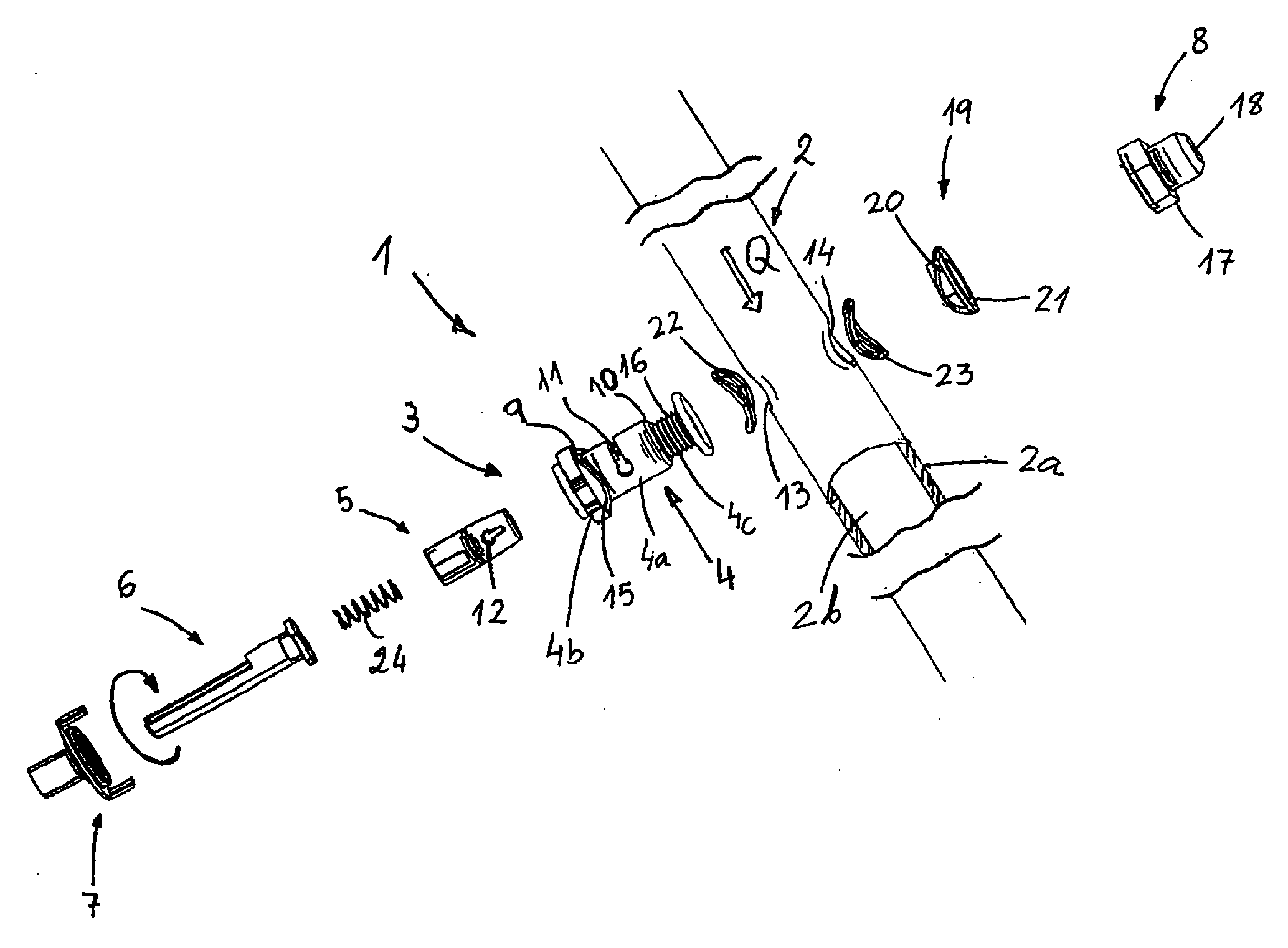
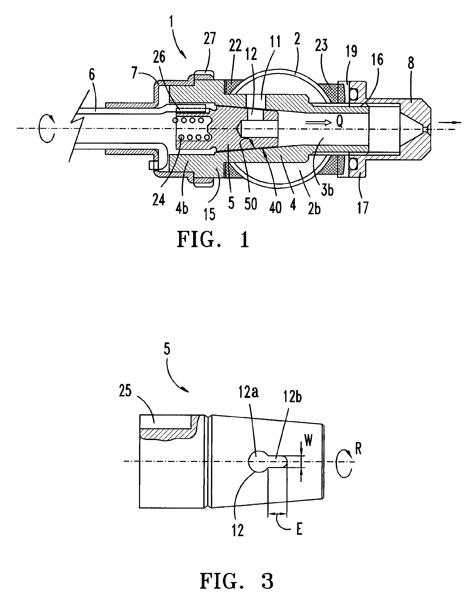
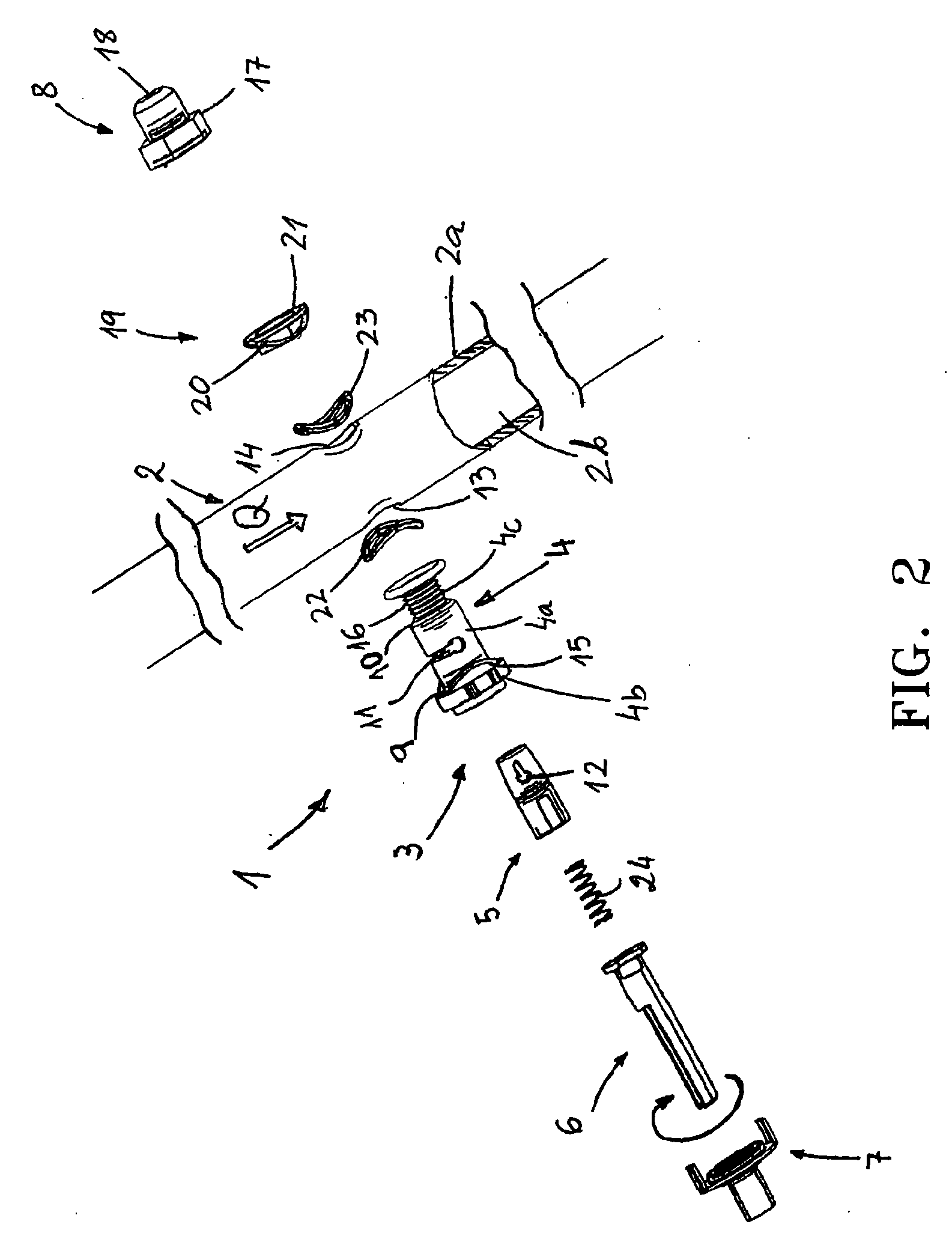
[0013]With reference to FIGS. 1 to 5, a device for distributing gas 1 in accordance with one embodiment is illustrated. As shown, the device comprises an elongated gas distribution pipe 2, preferably cylindrical, of the type that is connected at one end to a gas source of a domestic cooking appliance, and a number of rotary taps 3 integrated into the distribution pipe 2 that are distanced from each other for the individual supplying of a gas flow “Q” to a corresponding burner.

[0014]Each of taps 3 comprise a tap body 4 and a internal regulation member 5 that may be conical, the part of the body 4a that cooperates with the regulation of the gas flow “Q” being housed inside the pipe 2. The gas supplied by the source circulates through the inlet hole 2b of the pipe 2, and reaches the tap 3 first of all through a regulation groove 11 on the surface of the body 4a, and then through a rotary passage opening 12 towards the interior of the conical member 5, from where the gas is led to an ou...


PUM


Abstract

A gas tap for controlling the flow of a gas to a cooking appliance. In one embodiment, the gas tap includes a body and a rotatable regulation member positioned within the valve body, the valve body having a stationary groove for the inlet of gas from an exterior wall surface to an interior wall surface of the body, the regulation member having a passage opening for the inlet of gas from an exterior surface to an interior cavity of the regulation member, the passage opening moving with an angular rotation of the regulation member. The groove and passage opening are shaped, dimensioned and positioned relative to one another such that the regulation of an intermediate gas flow Qgra (a flow between Qmax and Qmin) is proportional to the angular displacement of the rotatable regulation member.

Description

CROSS-REFERENCE TO RELATED APPLICATIONS[0001]This application claims priority to PCT / ES2007 / 070121 filed Jun. 19, 2007, which claims priority to Spanish Patent Application No. U200601861, filed Aug. 7, 2006.TECHNICAL FIELD[0002]The present invention relates to a device for distributing a gas flow to a domestic cooking appliance, which may include a number of rotary taps integrated into the distribution pipe, for regulating the individual gas flow supplied to an outlet conduit of said tap.BACKGROUND[0003]There are known gas fuel distributors for a cooking appliance of the type mentioned above, such as that disclosed in WO 97 / 21960, which comprises various taps integrated in a distribution pipe, distanced from each other, and assembled with means for the airtight closure of the insertion holes on the tap body in the pipe.[0004]Each of the gas taps disclosed therein includes a body portion comprising a fixed generally hollow frusto-conical casing positioned within the distribution pipe...

Claims


Application Information

Patent Timeline
IPC IPC(8): F16K5/10
CPCF16K5/0214F16K5/103F23N2035/24F23N2035/16F23N1/007F23N2235/16F23N2235/24
Inventor ALBIZURI LANDA, INIGO
Owner COPRECITEC
Why Eureka
Try Eureka