System and method for using microgyros to measure the orientation of a survey tool within a borehole

Active Publication Date: 2005-10-13
GYRODATA
View PDF42 Cites 44 Cited by
  • Summary
  • Abstract
  • Description
  • Claims
  • Application Information

AI Technical Summary

Benefits of technology

[0015] For purposes of summarizing the invention, certain aspects, advantages and novel features of the invention have been described herein above. It is to be understood, however, that not necessarily all such advantages may be achieved in accordance with any par

Problems solved by technology

In addition, these HDD systems typically drill holes which reemerge as well.
Such wireline surveys thus require extensive time and effort to repeatably stop drilling, insert the survey tool into the borehole, and remove the survey tool (and perh

Method used


Image

  • System and method for using microgyros to measure the orientation of a survey tool within a borehole
  • System and method for using microgyros to measure the orientation of a survey tool within a borehole
  • System and method for using microgyros to measure the orientation of a survey tool within a borehole

Examples


Embodiment Construction

[0021] Making gyroscopic measurements of the orientation and position of a wireline geophysical instrument package using a survey tool or of a drilling tool while drilling using a measurement-while-drilling (MWD) survey tool is a challenging task due in part to the extreme conditions to which the survey tool is exposed. For example, the survey tool is often exposed to accelerations which can influence or disrupt measurements of the angular rotation rate about a sensing axis. Since some gyroscope errors are a function of sensed acceleration, small accelerations (e.g., fractions of the gravitational acceleration of 9.8 meters / sec 2) can cause significant angular rate errors. Vibrations can create oscillations in the output from the gyroscope, leading to an unfavorable random error increase. In addition, for gyroscopes using feedback loops, such high frequency vibrations can lead to undesirable errors.

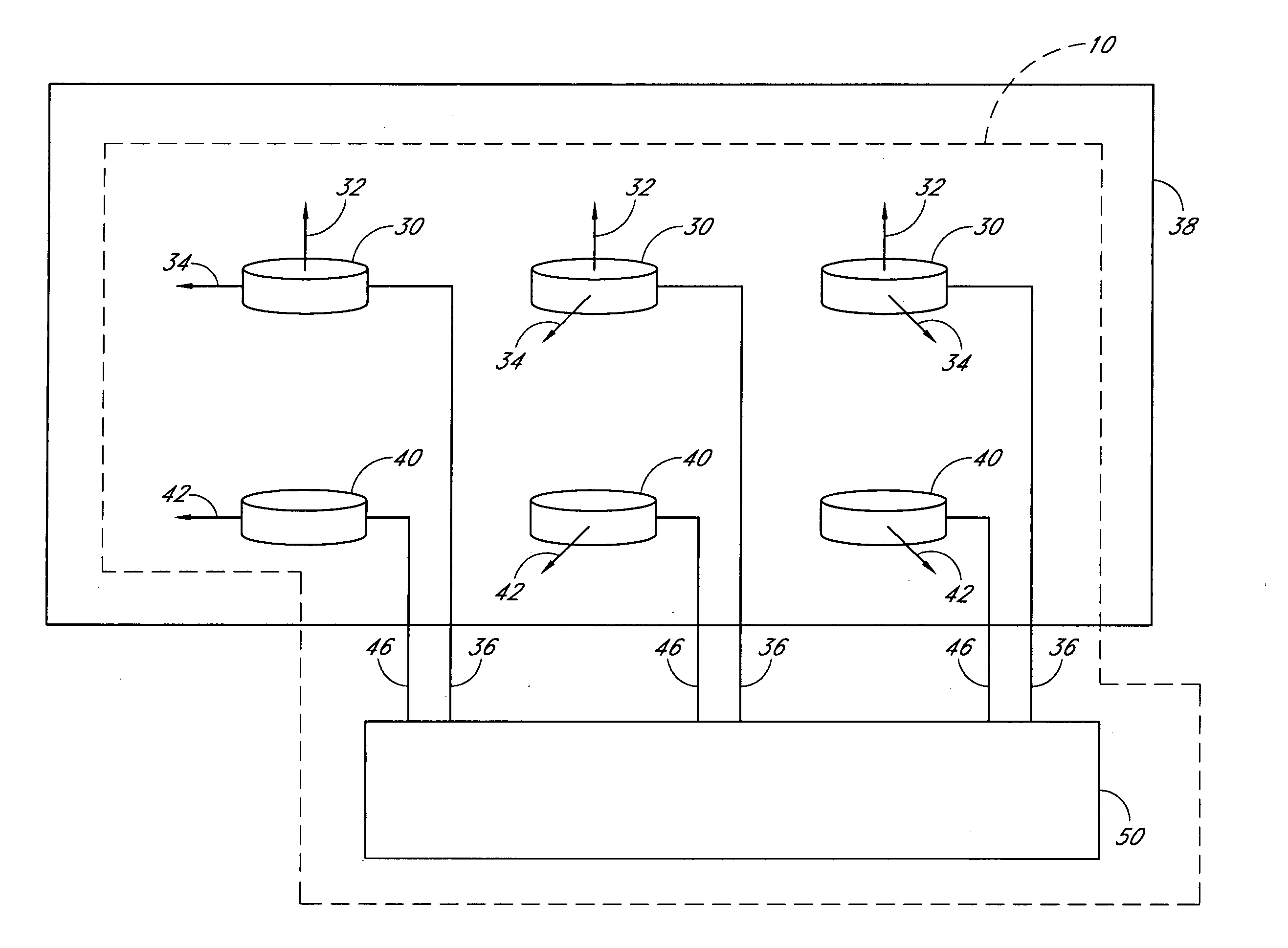
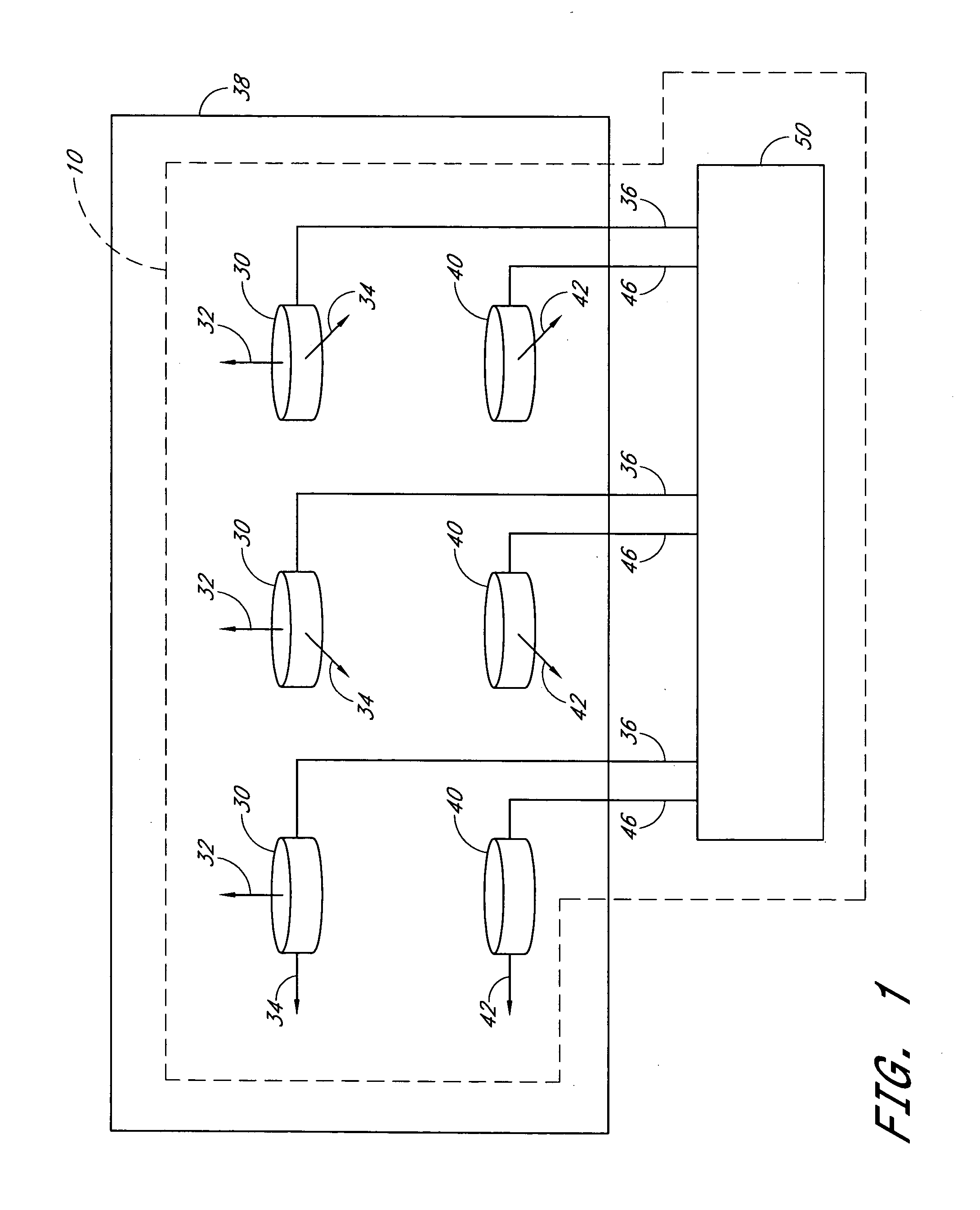
[0022]FIG. 1 schematically illustrates a survey tool 10 in accordance with embodimen...


PUM


Abstract

A system and method for determining an orientation of the survey tool within a borehole utilizes a survey tool including a plurality of rotation sensors each having a sensing axis and a direction of least acceleration sensitivity. The plurality of rotation sensors are mounted in a housing with their sensing axes generally parallel to one another and with their directions of least acceleration sensitivity generally non-parallel to one another. The survey tool further includes a controller adapted to calculate a weighted average of the detected angular rotation rates from the plurality of rotation sensors. The weighted average includes the detected angular rotation rate of each rotation sensor about its sensing axis weighted by the detected acceleration along its direction of least acceleration sensitivity.

Description

BACKGROUND OF THE INVENTION [0001] 1. Field of the Invention [0002] The present application relates generally to systems and methods for determining the orientation of a survey tool within a borehole. [0003] 2. Description of the Related Art [0004] Directional drilling for the exploration of oil and gas deposits advantageously provides the capability of generating boreholes which deviate significantly relative to the vertical direction (that is, perpendicular to the Earth's surface) by various angles and extents. In certain circumstances, directional drilling is used to provide a borehole which avoids faults or other subterranean structures (e.g., salt dome structures). Directional drilling is also used to extend the yield of previously-drilled wells by reentering and milling through the side of the previously-drilled well, and drilling a new borehole directed so as to follow the hydrocarbon-producing formation. Directional drilling can also be used to provide numerous boreholes beg...

Claims


Application Information

Patent Timeline
IPC IPC(8): G01C21/16
CPCE21B47/022G01C19/56G01C21/16
Inventor EKSETH, ROGERUTTECHT, GARY WILLIAM
Owner GYRODATA
Why Eureka
Try Eureka