Three-dimension display and fabricating method thereof

a three-dimensional display and fabrication method technology, applied in the field of display, can solve problems such as limiting the viewing position of a viewer, and achieve the effect of promoting the display quality of 3d images and reducing manufacturing costs

Active Publication Date: 2009-06-04
AU OPTRONICS CORP
View PDF10 Cites 47 Cited by
  • Summary
  • Abstract
  • Description
  • Claims
  • Application Information

AI Technical Summary

Benefits of technology

The present invention is a 3D-display that uses a patterned half-wave plate and a quarter-wave plate to produce left and right eye frames for different polarizations. This allows viewers to see 3D-images with a wider view angle and improved display quality compared to prior art. The optical axis of the quarter-wave plate is parallel to the optical axis of the patterned half-wave plate, and a single alignment layer is used to integrate the two plates, reducing manufacturing costs.

Problems solved by technology

The technical problem addressed in this patent text is how to make a display apparatus produce 3D images or pictures that can be viewed from multiple viewing positions without being dependent on the view angle.

Method used


Image

  • Three-dimension display and fabricating method thereof
  • Three-dimension display and fabricating method thereof
  • Three-dimension display and fabricating method thereof

Examples


first embodiment

[0039]Reference will now be made in detail to the present preferred embodiments of the invention, examples of which are illustrated in the accompanying drawings. Wherever possible, the same reference numbers are used in the drawings and the description to refer to the same or like parts.

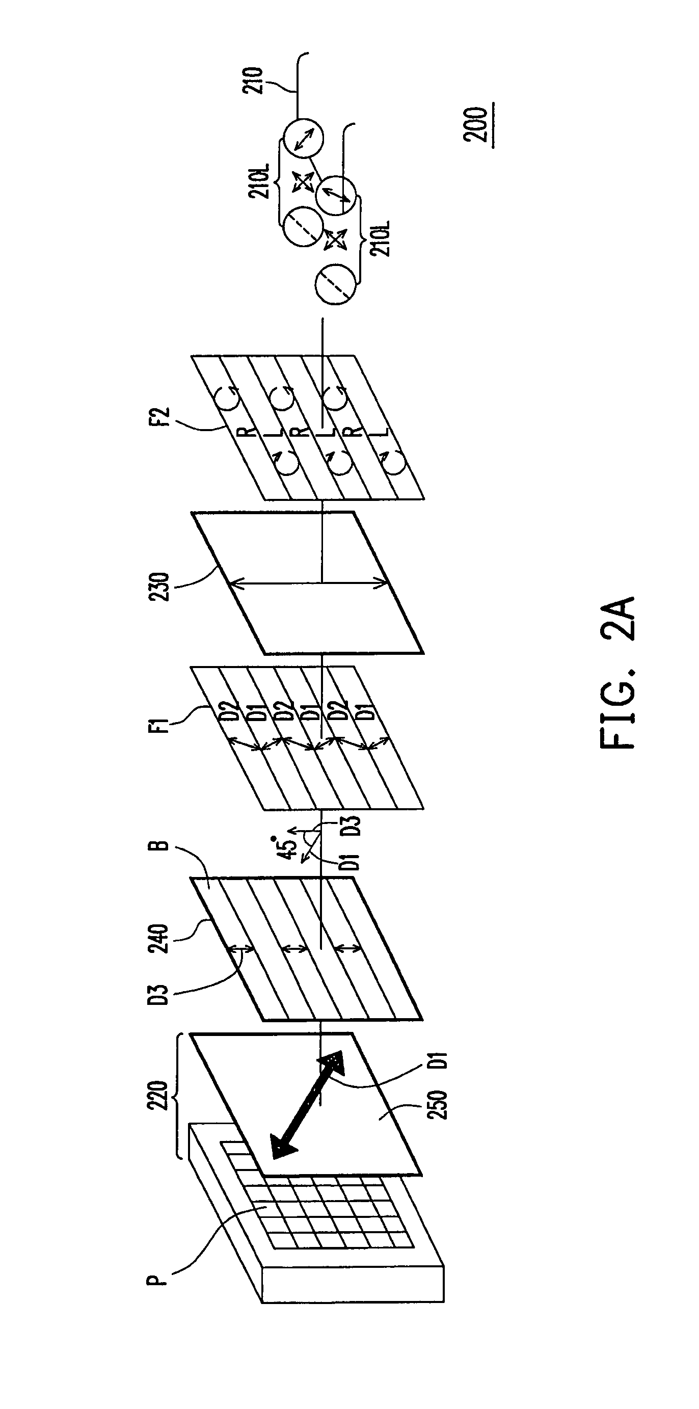
[0040]FIG. 2A is a diagram of a3-D display according to the first embodiment of the present invention. Referring to FIG. 2A, a 3D-display 200 is suitable for a viewer wearing a pair of circular polarized eyeglasses 210 to watch, wherein the circular polarized eyeglasses 210 have two circular polarized eyeglass lenses 210L with a left-handed circular polarization and a right-handed circular polarization and the circular polarized eyeglass lens 210L can be seen as a combination of a quarter-wave plate and a linear polarized plate as shown by FIG. 2A. In addition, the 3D-display 200 includes a flat display panel 220, a quarter-wave plate 230 and a patterned half-wave plate 240. In the embodiment, the pa...

second embodiment

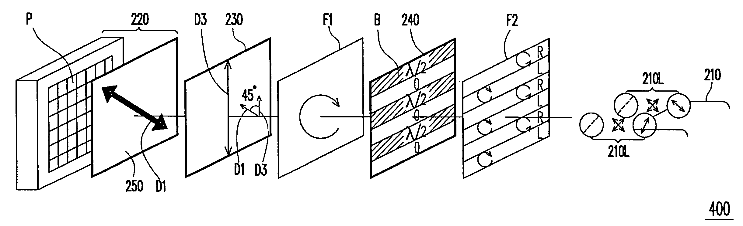
[0051]FIG. 5 is a diagram of a3-D display according to the second embodiment of the present invention. Referring to FIG. 5, a 3D-display 400 is similar to the 3D-display 200 of the first embodiment except that the quarter-wave plate 230 and the patterned half-wave plate 240 have different disposing positions from that of the 3D-display 200. The quarter-wave plate 230 of the 3D-display 400 herein is disposed on the flat display panel 220, the patterned half-wave plate 240 is disposed on the quarter-wave plate 230 and the quarter-wave plate 230 is located between the patterned half-wave plate 240 and the flat display panel 220.

[0052]In the embodiment, the flat display panel 220 has an upper polarized plate 250, wherein the extension direction of the optical axis of the upper polarized plate 250 is D1, which makes the flat display panel 220 suitable to display the linear polarized image with the polarization D1. Next, the quarter-wave phase retardation provided by the quarter-wave plat...


PUM


Abstract

A three-dimension display suitable for a viewer wearing a pair of eyeglasses is disclosed. The eyeglasses have two circular polarized eyeglass lenses with different polarizations. The three-dimension display includes a flat display panel, a quarter-wave plate and a patterned half-wave plate. The flat display panel has a plurality of pixels arranged in an array, wherein the flat display panel is suitable to display a linear polarized image. The quarter-wave plate is disposed between the flat display panel and the eyeglasses. The patterned half-wave plate is disposed between the flat display panel and the eyeglasses, wherein the patterned half-wave plate corresponds to a part of the pixels. The present invention also provides a fabrication method of a three-dimension display.

Description


Claims


Application Information

Patent Timeline
Owner AU OPTRONICS CORP
Why Eureka
Try Eureka