Image Forming Device, and Method and Computer Readable Medium Therefor

Active Publication Date: 2009-06-04
BROTHER KOGYO KK
View PDF13 Cites 20 Cited by
  • Summary
  • Abstract
  • Description
  • Claims
  • Application Information

AI Technical Summary

Problems solved by technology

In such an image forming device, when positional deviations are caused among the respective toner images transferred onto the sheet by the image forming units, a formed image becomes a low-quality one.
Meanwhile, in the image forming device, the accuracies of the image forming positions are likely to vary due to operations of opening and closing a cover, and therefore it may lead to the deviations of the image forming positions.
However, the aforementioned image forming device has a problem that the positional deviation detection is performed each t

Method used


Image

  • Image Forming Device, and Method and Computer Readable Medium Therefor
  • Image Forming Device, and Method and Computer Readable Medium Therefor
  • Image Forming Device, and Method and Computer Readable Medium Therefor

Examples


first embodiment

[0031]A first embodiment will be explained referring to FIGS. 1 to 7.

(Overall Configuration of Printer)

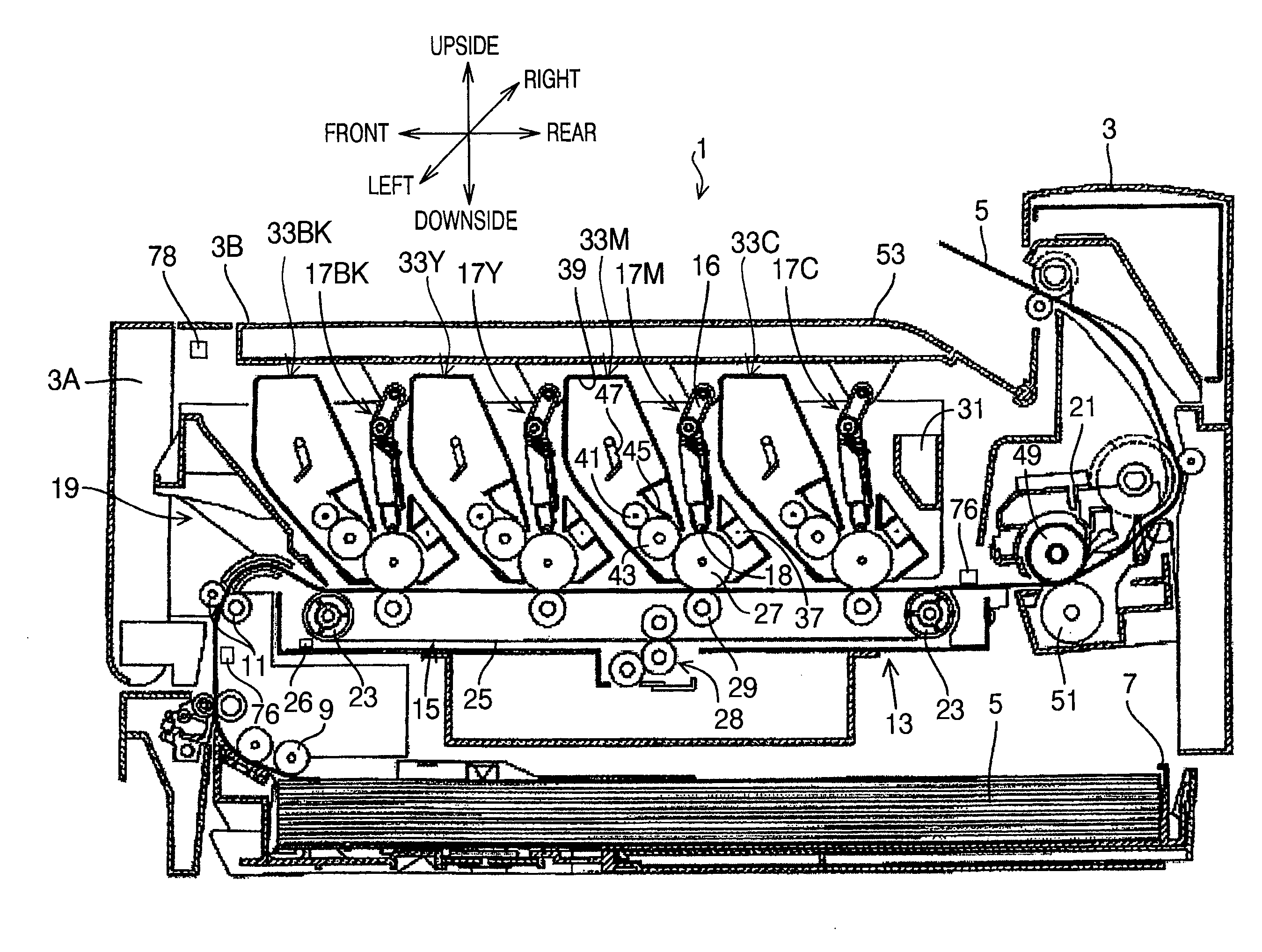
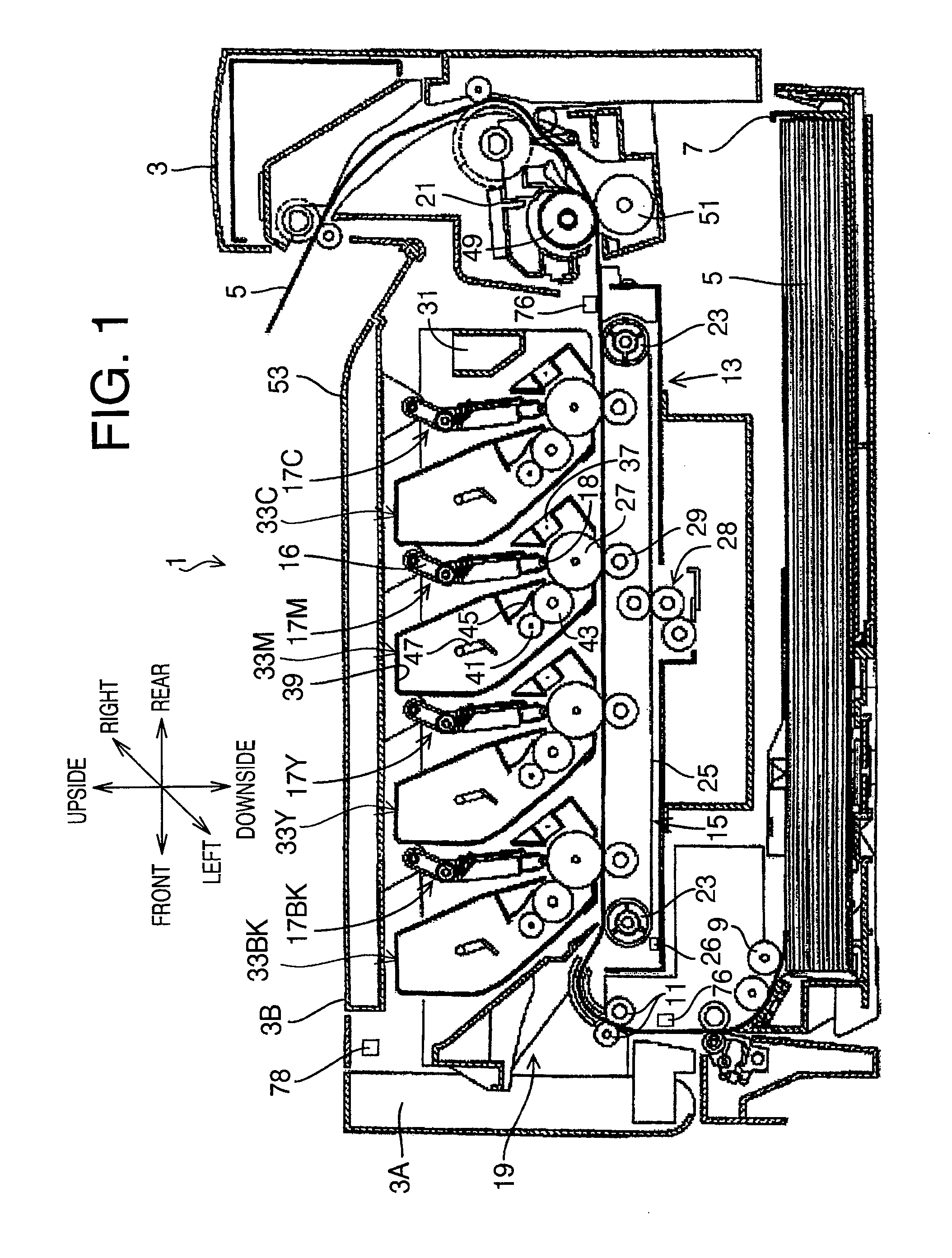
[0032]FIG. 1 is a cross-sectional side view schematically showing a configuration of a printer 1 in the first embodiment according to aspects of the present invention. It is noted that the following description will be given under an assumption that a left side of FIG. 1 is defined as a front side of the printer 1. In addition, the printer 1 is a color printer configured to form a color image with coloring agents of four colors (black BK, yellow Y, magenta M, and cyan C). Hereinafter, when each constituent component of the printer 1 is required to be distinguished by the color, the constituent component is represented by a reference number with a suffix denoting a corresponding color such as “BK,”“Y,”“M,” and “C” added to an end thereof.

[0033]The printer 1 is provided with a main body casing 3. At a bottom of the main body casing 3, a sheet feed tray 7 is provided, which is configu...

second embodiment

[0073]FIG. 8 is a flowchart showing a procedure of a control process for printing and positional deviation correction in a second embodiment according to aspects of the present invention. FIG. 9 is a time chart showing a time relationship among events such as cover opening-closing operations, a positional deviation detecting operation, and print requests in the second embodiment. The second embodiment is different from the first embodiment in part of the control process for printing and positional deviation correction. The other parts of the second embodiment are the same as those of the first embodiment. Accordingly, the same elements (steps) between the first and second embodiments will be given the same reference characters, and explanation thereon will be omitted. Hereinafter, only differences between the first and second embodiments will be described.

[0074]When a paper jam is once caused, for example, for a reason that a jammed sheet is completely removed, thereafter, a paper j...

third embodiment

[0084]FIG. 10 is a flowchart showing part of a procedure of a control process for printing and positional deviation correction in a third embodiment according to aspects of the present invention. FIG. 11 is a time chart showing a time relationship among events such as cover opening-closing operations, a positional deviation detecting operation, and print requests in the third embodiment. The control process for printing and positional deviation correction in the third embodiment is different from that of the second embodiment in the steps between (A) and (B) surrounded by a dashed line in FIG. 8. FIG. 10 illustrates alternative steps for the steps between (A) and (B) surrounded by the dashed line in FIG. 8. The other steps of the control process for printing and positional deviation correction in the third embodiment are the same as those of the second embodiment. Accordingly, the same elements (steps) between the second and third embodiments will be given the same reference charact...


PUM


Abstract

An image forming device includes a main body casing, a cover configured to be openable and closable with respect to the main body casing, a sensing unit configured to sense an opening-closing operation of the cover, a forming unit configured to form an image on a sheet, a detecting unit configured to perform a detecting operation to detect a deviation of an image forming position of the image to be formed by the forming unit, an accepting unit configured to accept a print request, and a control unit configured to control the detecting unit to perform the detecting operation in response to the print request being accepted when the sensing unit senses an opening-closing operation of the cover after execution of a previous detecting operation, and thereafter to control the forming unit to form the image in the image forming position corrected to cancel the deviation detected in the detecting operation.

Description

CROSS-REFERENCE TO RELATED APPLICATION[0001]This application claims priority under 35 U.S.C. §119 from Japanese Patent Application No. 2007-311140 filed on Nov. 30, 2007. The entire subject matter of the application is incorporated herein by reference.BACKGROUND[0002]1. Technical Field[0003]The following description relates to one or more techniques to avoid unnecessary correction for canceling deviations of image forming positions in an image forming device.[0004]2. Related Art[0005]An image forming device such as a color electrophotographic printer has been known, which includes a plurality of image forming units aligned along a sheet carrying belt such that toner images of respective different colors are sequentially transferred by the image forming units onto a sheet being conveyed on the sheet carrying belt. In such an image forming device, when positional deviations are caused among the respective toner images transferred onto the sheet by the image forming units, a formed ima...

Claims


Application Information

Patent Timeline
IPC IPC(8): G06K15/00
CPCG03G2215/0161G03G15/0194G03G21/1633G03G2221/169
Inventor KUSHIDA, TSUYOSHI
Owner BROTHER KOGYO KK
Why Eureka
Try Eureka