Color filter substrate and display device

a color filter substrate and substrate technology, applied in the field of color filter substrates and display devices, can solve the problems of limited color reproduction range insufficient mixing of color lights, etc., and achieve the effect of reducing the color separation of a straight lin

Inactive Publication Date: 2009-06-04
SHARP KK
View PDF21 Cites 31 Cited by
  • Summary
  • Abstract
  • Description
  • Claims
  • Application Information

AI Technical Summary

Benefits of technology

[0009]In order to overcome the problems described above, preferred embodiments of the present invention provide a color filter substrate and a color display device, each capable of

Problems solved by technology

In such a combination, however, a range of color which can be observed by human eyes can be only partly displayed, and therefore the color reproduction range is limited.
Therefore, the color lights are insufficiently mixed.
Also in this configuration, however, t

Method used


Image

  • Color filter substrate and display device
  • Color filter substrate and display device
  • Color filter substrate and display device

Examples


first preferred embodiment

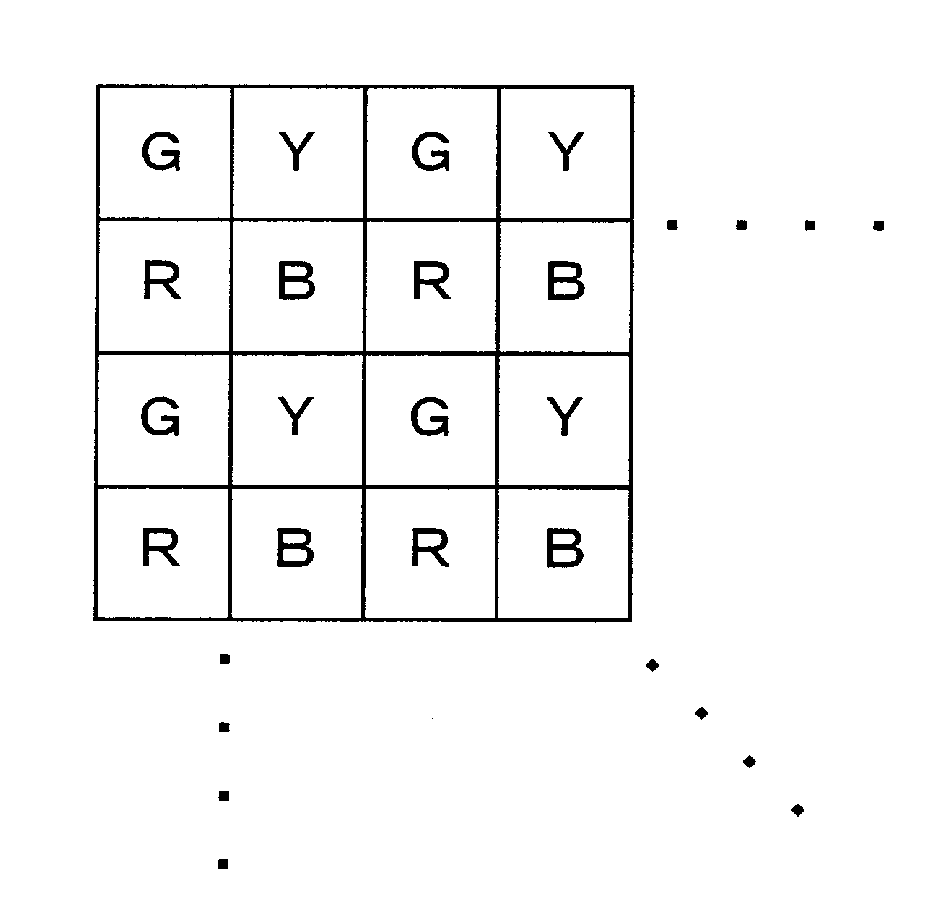
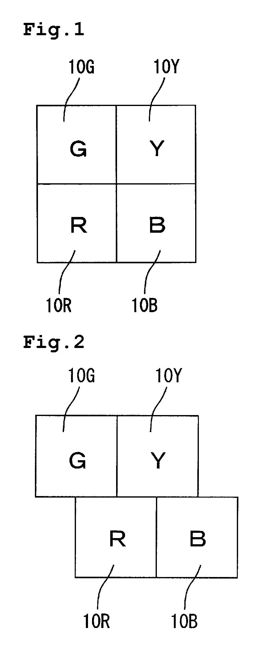
[0068]FIG. 1 is a planar view schematically showing a pixel configuration of a color filter substrate according to a first preferred embodiment of the present invention. According to the color filter substrate of the present preferred embodiment, a red colored layer 10R, a green colored layer 10G, a yellow colored layer 10Y, and a blue colored layer 10B are arrayed inside each pixel in a matrix pattern. The color array of these colored layers is in order of red (R), green (G), yellow (Y), blue (B) in the clockwise direction and is not the same as the order of hue (R, Y, G, B).

[0069]With the red colored layer 10R, the green colored layer 10G, the yellow colored layer 10Y, and the blue colored layer 10B, dominant wavelengths of the transmission spectrums are 607 nm, 573 nm, 550 nm, and 466 nm, respectively. Further, with respect to a luminance ratio, a ratio of (red colored layer 10R):(green colored layer 10G): (yellow colored layer 10Y): (blue colored layer 10B)=5:10 to 16:2.

second preferred embodiment

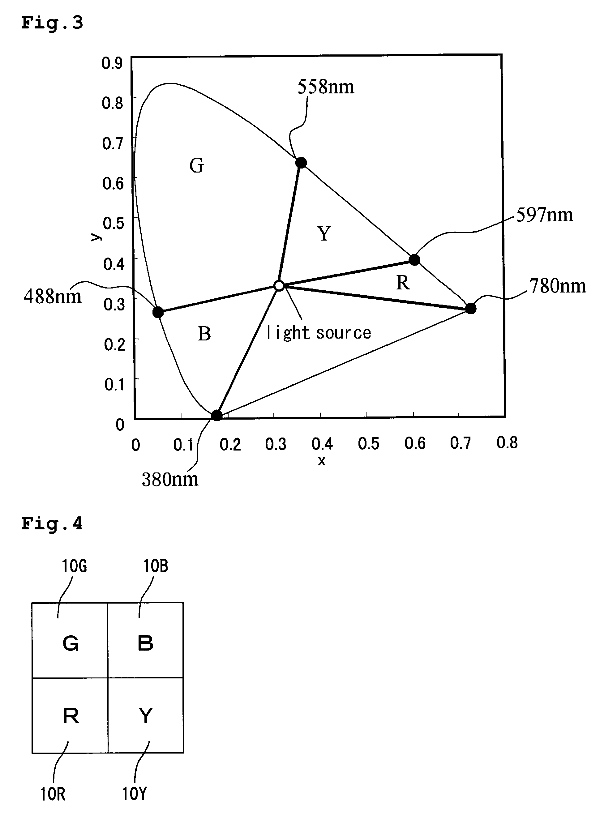
[0070]FIG. 4 is a planar view schematically showing a pixel configuration of a color filter according to a second preferred embodiment. According to the color filter in the second preferred embodiment, the color array of the colored layers is in order of R, G, B, Y in the clockwise direction, which is different from that in the first preferred embodiment. However, the color filter substrate is the same as that in the first preferred embodiment in that the color array of the colored layers is not the same as the order of hue and that the red colored layer 10R and the green colored layer 10 G which are opponent colors, the yellow colored layer 10Y and the blue colored layer 10B which are opponent colors, are adjacently arranged to each other, respectively.

third preferred embodiment

[0077]FIG. 8 is a planar view schematically showing a color filter substrate according to the third preferred embodiment of the present invention. According to the color filter substrate in the present preferred embodiment, the red colored layer 10R, the green colored layer 10G, the yellow colored layer 10Y, and the blue colored layer 10B are arrayed inside every pixel in a stripe pattern. The color array of these colored layers is in order of red (R), green (G), yellow (Y), blue (B) in the right direction in FIG. 8, which is not the same as the order of hue (R, B, G, Y).

[0078]The dominant wavelengths of the transmission spectrums and the luminance ratios of the colored layers having respective colors are the same as those in the first preferred embodiment.

Fourth Through Sixth Preferred Embodiments

[0079]FIGS. 10 to 12 are planar views schematically showing pixel configurations of color filter substrates according to the fourth through Sixth preferred embodiments of the present inven...


PUM


Abstract

A color filter substrate and a display device are each capable of reducing color separation of a straight line displayed with a mixed color and particularly color separation of a straight white line displayed with a mixed color on a black background. The color filter substrate is a color filter substrate including colored layers of at least four colors, arrayed inside a pixel region, wherein at least one pair of colored layers that are not next to each other when the colored layers of all the colors are arrayed in order of hue is adjacently arranged to each other inside the pixel region.

Description

BACKGROUND OF THE INVENTION[0001]1. Field of the Invention[0002]The present invention relates to color filter substrates and display devices. More specifically, the present invention relates to a color filter substrate preferably used in multi-primary color display devices which display characters, images, moving images, and the like; and a display device such as a liquid crystal display device, and such a color filter substrate and a display device are used in a cellular telephone, for example.[0003]2. Description of the Related Art[0004]A color filter substrate is one member equipped with a display device to provide color display, and generally, on such a color filter substrate, a plurality of colored layers is regularly arranged in every pixel. As a combination of colors of such colored layers constituting the pixel, three primary colors of red (R), green (G), and blue (B) are used. In such a combination, however, a range of color which can be observed by human eyes can be only p...

Claims


Application Information

Patent Timeline
IPC IPC(8): G02B5/20
CPCG02F2201/52G02B5/201
Inventor ITOU, AKIKONAKAMURA, KOHZOHUEKI, SHUNTAGUCHI, TOKIO
Owner SHARP KK
Why Eureka
Try Eureka