Led-based lighting device with asymmetrically distributed LED chips

a technology of led chips and led chips, applied in the field of led chips with asymmetric mounting, can solve the problems of spatially dependent differences in spectral composition, severe coloration in the fringe of a pattern, etc., and achieve the effect of reducing color separation

Active Publication Date: 2018-03-08
KONINKLJIJKE PHILIPS NV
View PDF3 Cites 0 Cited by
  • Summary
  • Abstract
  • Description
  • Claims
  • Application Information

AI Technical Summary

Benefits of technology

[0006]An object of the present invention is to provide a lighting device which at least partly overcomes some of the problems stated above. In particular, it is an object to provide a lighting device with reduced color separation.

Problems solved by technology

A problem with using LED-based lighting devices showing COA in spot applications is that severe coloration in the fringe of a pattern can occur, especially for narrow light beams.
In a lighting device, the placement of the LED chips results in spatially depending differences in spectral composition in the non-collimated light.

Method used


Image

  • Led-based lighting device with asymmetrically distributed LED chips
  • Led-based lighting device with asymmetrically distributed LED chips
  • Led-based lighting device with asymmetrically distributed LED chips

Examples


Embodiment Construction

[0045]Exemplifying embodiments will now be described more fully hereinafter with reference to the accompanying drawings, in which currently preferred embodiments are shown. The invention may, however, be embodied in many different forms and should not be construed as limited to the embodiments set forth herein; rather, these embodiments are provided for thoroughness and completeness, and fully convey the scope of the invention to the skilled person.

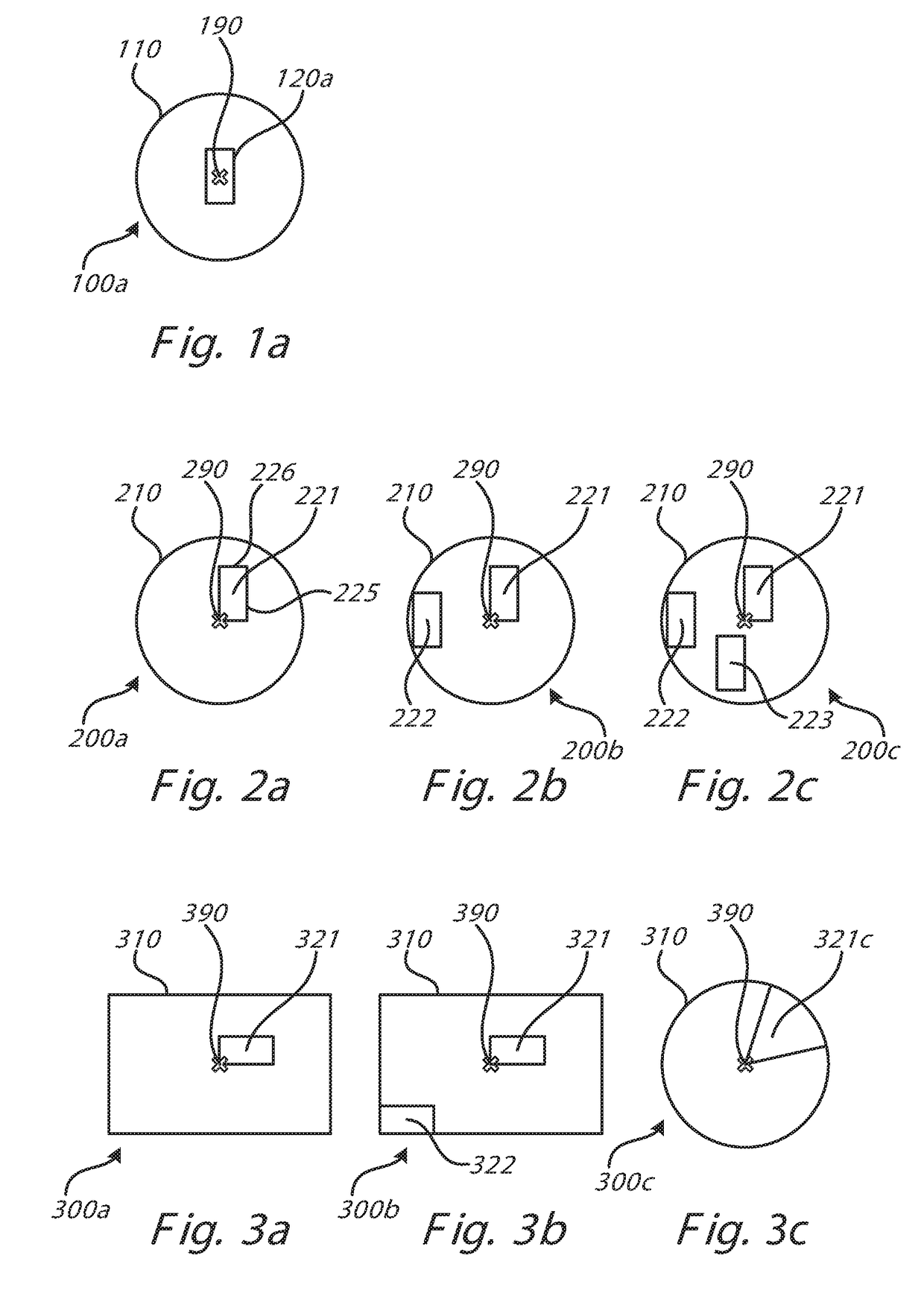
[0046]With reference to FIG. 1a, a known system comprising a light emitting chip is described.

[0047]FIG. 1a shows a schematic illustration of a typical one chip layout for a LED based lighting device 100a. A chip 120a is centered with respect to the center, or central axis, 190 of a base 110. The chip emits light which then propagates out from the device.

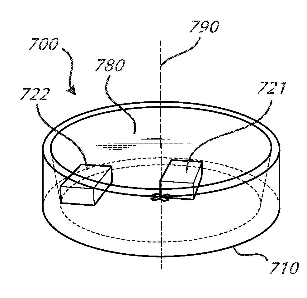
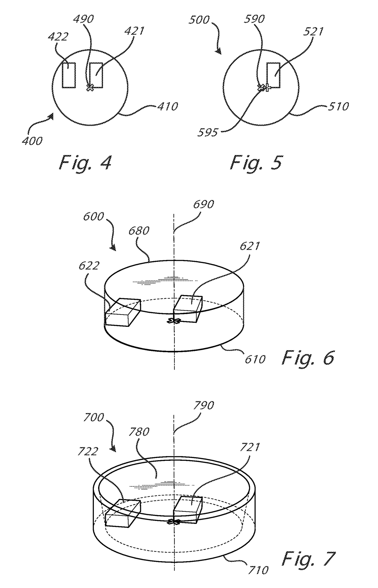
[0048]FIGS. 2a, b and c show a schematic illustration of a lighting device according to embodiments of the invention with one, two or three light emitting chips, respectively.

[0049]The li...


PUM


Abstract

A lighting device is provided that allows a reduced color separation. The lighting device is configured to emit light along an output direction. The lighting device comprises a base, two or more light emitting diode, LED, chips and a light transmissive dielectric material. The two or more LED chips are asymmetrically distributed on the base and are configured to emit light in the output direction. The light transmissive dielectric material may be embedding the two or more chips and includes luminescent material. A first chip of the one or more LED chips is arranged so that one corner of the first chip coincides, or at least closely, coincides with a central axis of the lighting device.

Description

TECHNICAL FIELD[0001]The present specification generally relates to the field of lighting devices based on light emitting diodes (LEDs) and particularly discloses a lighting device with asymmetrically mounted LED chips.TECHNICAL BACKGROUND[0002]Generally, mid and low power LED-based lighting devices comprise a white cup, one or more LED chips for emitting blue light and a phosphorous light transmitting dielectric for converting the wavelength of the emitted blue light. The emitted blue light reaching the wavelength converting phosphor will usually result in yellow light (depending on the properties of the wavelength converting phosphor). Although some of the light output from the LED-based lighting device may be yellow, the output light will have a different spectral composition due to the fact that various light rays emitted at different angles from the LED chips pass an unequal amount of phosphor.[0003]Hence, there will be a spatially depending difference in spectral composition i...

Claims


Application Information

Patent Timeline
Patent Type & Authority Applications(United States)
IPC IPC(8): H01L33/48H01L33/58H01L33/50H01L25/075
CPCH01L33/486H01L33/58H01L33/508H01L25/0753H01L25/075F21Y2115/20
Inventor DROSS, OLIVERVISSENBERG, MICHEL CORNELIS JOSEPHUS MARIE
Owner KONINKLJIJKE PHILIPS NV
Why Eureka
Try Eureka