Bandwidth reservation reuse in dynamically allocated ring protection and restoration technique

a technology of dynamic allocation and bandwidth reservation, applied in the field of communication networks, can solve the problems of high price to be paid for this protection, span outage, service disruption becoming increasingly costly, etc., and achieve the effect of maximizing switching speed

Inactive Publication Date: 2009-06-04
ADTRAN
View PDF87 Cites 47 Cited by
  • Summary
  • Abstract
  • Description
  • Claims
  • Application Information

AI Technical Summary

Benefits of technology

[0014]A node monitors the status of each link for which it is at the receiving end, e.g. each of its ingress links, to detect a fault. The detection of such a fault causes a highest-priority link status broadcast message to be sent to all nodes. Processing at each node of the information contained in the link status broadcast message results in reconfiguration of a routing table within each node so as to identify the optimum routing of source traffic to the destination node after the fault. Hence, all nodes know the status of the network and all independently identify the optimal routing path to each destination node when there is a fault in any of the links. The processing is designed to be extremely efficient to maximize switching speed.

Problems solved by technology

As data services become increasingly mission-critical to businesses, service disruptions become increasingly costly.
A type of service disruption that is of great concern is span outage, which may be due either to facility or equipment failures.
Unfortunately, there is a high price to be paid for this protection.

Method used


Image

  • Bandwidth reservation reuse in dynamically allocated ring protection and restoration technique
  • Bandwidth reservation reuse in dynamically allocated ring protection and restoration technique
  • Bandwidth reservation reuse in dynamically allocated ring protection and restoration technique

Examples


Embodiment Construction

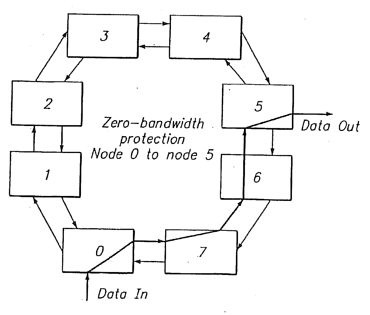
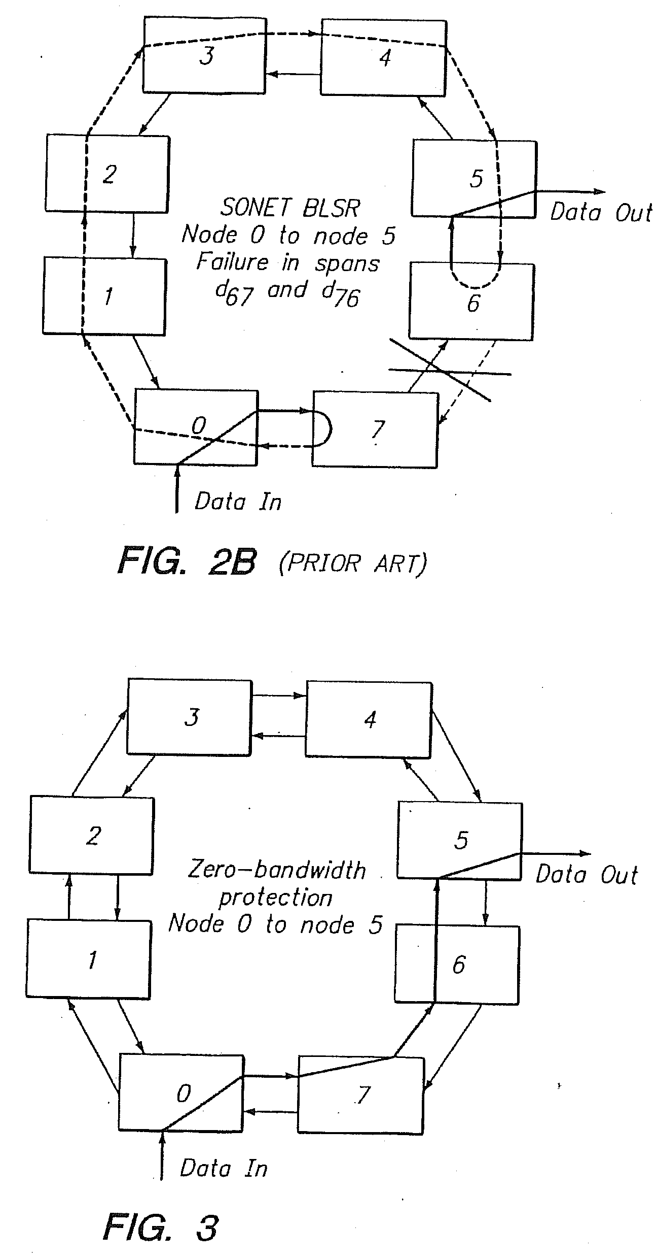
[0026]The purpose of the invention described herein is to achieve fast protection in a ring network while providing for efficient network capacity utilization. Certain aspects of the preferred embodiment are:

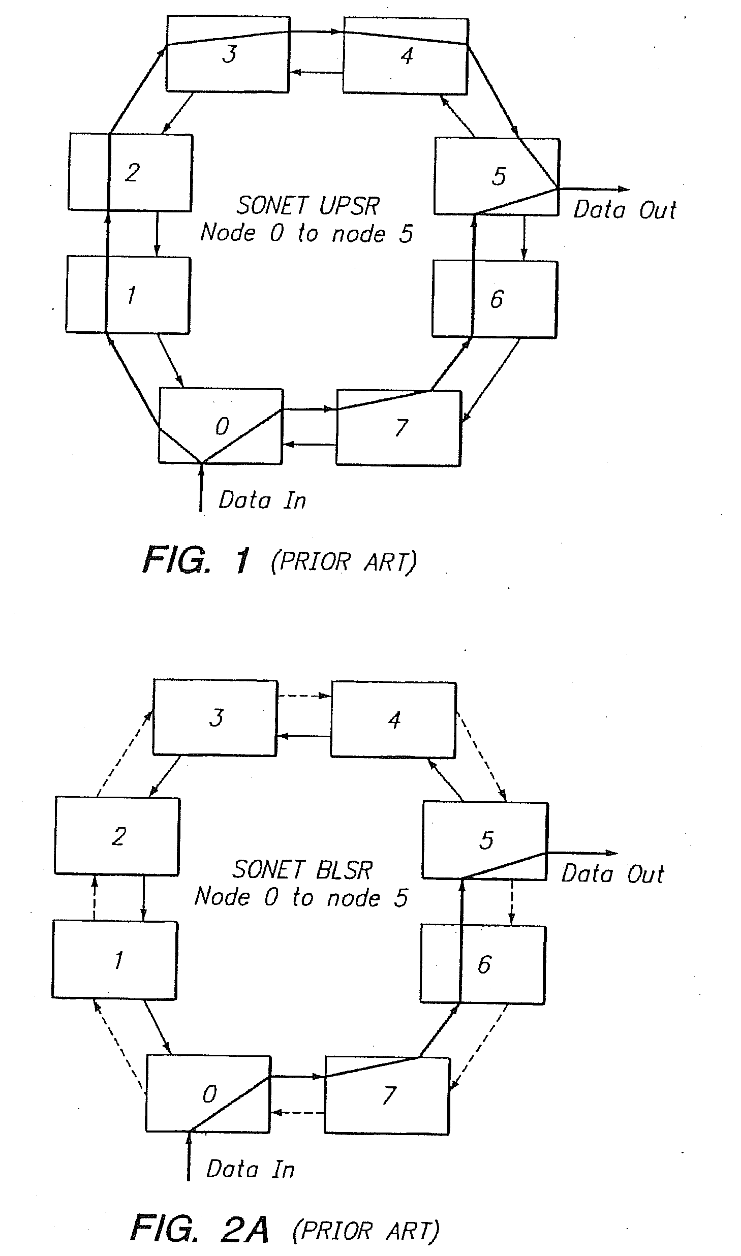
[0027]a. Transmission of a given packet between two nodes in only one direction around the ring (rather than in both directions as is done in SONET UPSR).

[0028]b. Differentiation between “protected” and “unprotected” traffic classes.

[0029]c. A fast topology communication mechanism to rapidly communicate information about a span break to all nodes in the ring.

[0030]d. A fast re-routing / routing table update mechanism to re-route paths impacted by a span break the other direction around the ring.

[0031]e. An optional interim wrapping mechanism that may be used to further increase protection switching speed.

[0032]These aspects are described in more detail below.

Unidirectional Transmission

[0033]A given packet / flow between two nodes is transmitted in only a single direction around the ...


PUM


Abstract

The disclosed network includes two rings, wherein a first ring transmits data in a clockwise direction, and the other ring transmits data in a counterclockwise direction. The traffic is removed from the ring by the destination node. During normal operations (i.e., all spans operational), data between nodes can flow on either ring. Thus, both rings are fully utilized during normal operations. The nodes periodically test the bit error rate of the links (or the error rate is constantly calculated) to detect a fault in one of the links. The detection of such a fault sends a broadcast signal to all nodes to reconfigure a routing table within the node so as to identify the optimum routing of source traffic to the destination node after the fault.

Description

REFERENCE TO CROSS-RELATED APPLICATIONS[0001]This application claims priority, under 35 U.S.C. 120, as a continuation application of U.S. application Ser. No. 10 / 854,049, filed on May 26, 2004, entitled “ROUTING SWITCH DETECTING CHANGE IN SESSION IDENTIFIER BEFORE RECONFIGURING ROUTING TABLE” which, in turn, incorporates by reference U.S. application Ser. No. 09 / 519,442 (now U.S. Pat. No. 6,865,149), filed on Mar. 3, 2000, entitled “DYNAMICALLY ALLOCATED RING PROTECTION AND RESTORATION TECHNIQUE”, the contents of each application being hereby incorporated by reference in their entirety.FIELD OF THE INVENTION[0002]This invention relates to communication networks and, in particular, to network employing rings.BACKGROUND[0003]As data services become increasingly mission-critical to businesses, service disruptions become increasingly costly. A type of service disruption that is of great concern is span outage, which may be due either to facility or equipment failures. Carriers of voice ...

Claims


Application Information

Patent Timeline
Patent Type & Authority Applications(United States)
IPC IPC(8): H04J3/14H04L12/56H04L1/00H04L29/12
CPCH04L29/12009H04L29/12584H04L29/12783H04L29/12839H04L29/12943H04L61/6072H04L45/021H04L61/2596H04L61/35H04L61/6022H04L45/02H04L61/00H04L2101/622H04L2101/672
Inventor FAN, JASON C.JOGALEKAR, PRASAD P.BANNAI, VINAY K.
Owner ADTRAN
Why Eureka
Try Eureka