Transformable intravenous pole

a technology of intravenous poles and transverse holes, which is applied in the direction of liquid springs, loading/unloading vehicle arrangments, transportation items, etc., can solve the problems of unsatisfactory mobile iv poles, impose significant burdens on hospital staff, and suffer from unsatisfactory forms

Active Publication Date: 2009-06-04
SKYTRON CORP
View PDF9 Cites 19 Cited by
  • Summary
  • Abstract
  • Description
  • Claims
  • Application Information

AI Technical Summary

Benefits of technology

[0017]At least one embodiment of the invention is directed to an IV pole system further comprising a pole mount. The pole mount comprises a horizontally sliding bar engaged to both a vertically extending support bar and at least one engagement member. The vertically extending support bar comprises an elevating mechanism and one or more gripping members. The gripping members are constructed and arranged for engagement to the mast. The elevating mechanism is constructed and arranged to adjust a vertical position of the mast. The horizontally sliding bar is constructed and arranged to adjust a horizontal separation distance between the at least one engagement member and the vertically extending support bar. The at least one engagement member can be constructed and arranged to engage a hospital bed. A bumper tail can be positioned around at least a portion of the bed. The bumper rail bulges farther from the bed at bed corners than from other bed locations. The system can further comprise a support bar engaged to the elevating member which is constructed and arranged to lift the bar. A biasing mechanism can exert a force on the horizontally sliding bar reducing the separation distance between the at least one engagement member and the vertically extending support bar. The horizontally sliding bar can have an inner portion in a telescoping relationship to the outer portion. The horizontally sliding bar can be pivotably engaged to the at least one engagement member.

Problems solved by technology

These IV poles, however, suffer from a number of drawbacks.
One unsatisfactory form of a mobile IV pole is a pole permanently attached to, and using out of, the patient transportation device such as that described in published US Patent Application 2006 / 0243500A1.
This form imposes significant burdens on hospital staff as each time the patient is moved, pumps and fluid bags must both be transferred onto the transportation device before the patient is moved, and then again the pumps and fluid bags must be transferred off of the transportation device once the patient arrives at their destination.
The repeated transferal of bags and pumps increases the risks of bags or pumps being dropped leading to wasted medicines needing replacement and wasted environmental services cleaning up spills as well as damage occurring to expensive pumps and equipment.
Similarly the permanently attached pole makes the transportation device bulky causing awkward and difficult movement, storage, and maintenance.
In the case of beds, permanently attached poles render the beds particularly bulky, and difficult to maneuver.
Other problems relate to difficulty in linen changes.
Further, beds with poles significantly increase the difficulty of patient transfer into and out of the bed.
Most seriously of all, constant removal and re-attachment of IV bags and pumps increases the risks of IV leads being strained or pulled entirely from the patient's body, complicating a patient's treatment and potentially putting the individual at risk of infection or improper treatment.
Another unsatisfactory form of mobile IV pole is a free standing wheeled pole that is moved alongside the patient transfer apparatus such as that described in published US Patent Application 2006 / 0222341A1.
This device unfortunately also imposes significant burdens on hospital staff.
Because patient transfer apparatuses may be heavy, and not designed for one handed pushing, repeatedly utilizing one person to simultaneously move both the pole and the transfer apparatus causes significant strain, which often results in back and sprain injuries in medical personnel.
Also, such pushing increases the risk of injury to a patient in that the pole may tip over onto the patient or that the patient transfer apparatus may strike walls or objects and aggravate an injury.
The alternative of utilizing multiple medical personnel to transport a single patient is inefficient and cost prohibitive in an era of scarce nurses and other medical personnel.

Method used


Image

  • Transformable intravenous pole
  • Transformable intravenous pole
  • Transformable intravenous pole

Examples


Embodiment Construction

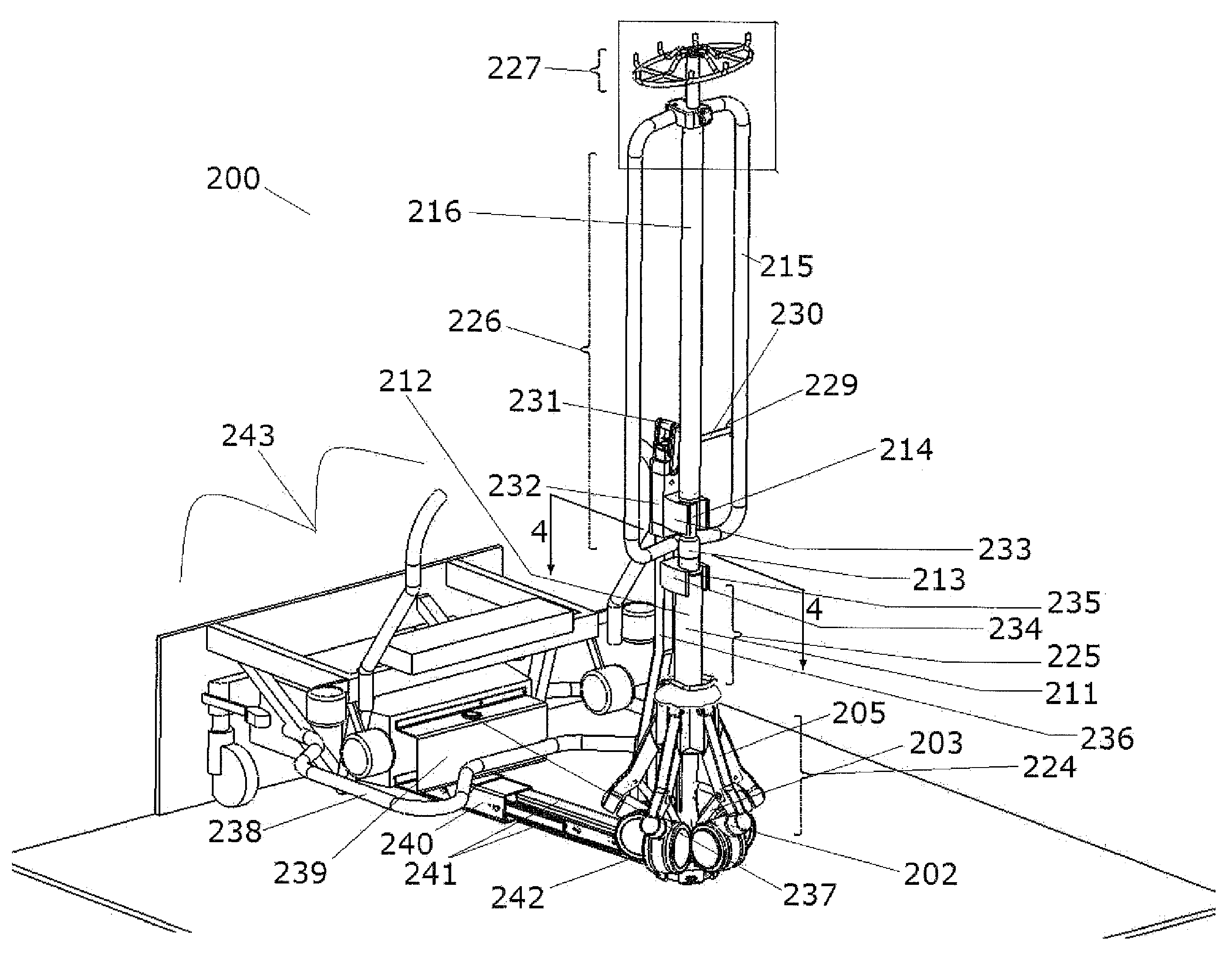
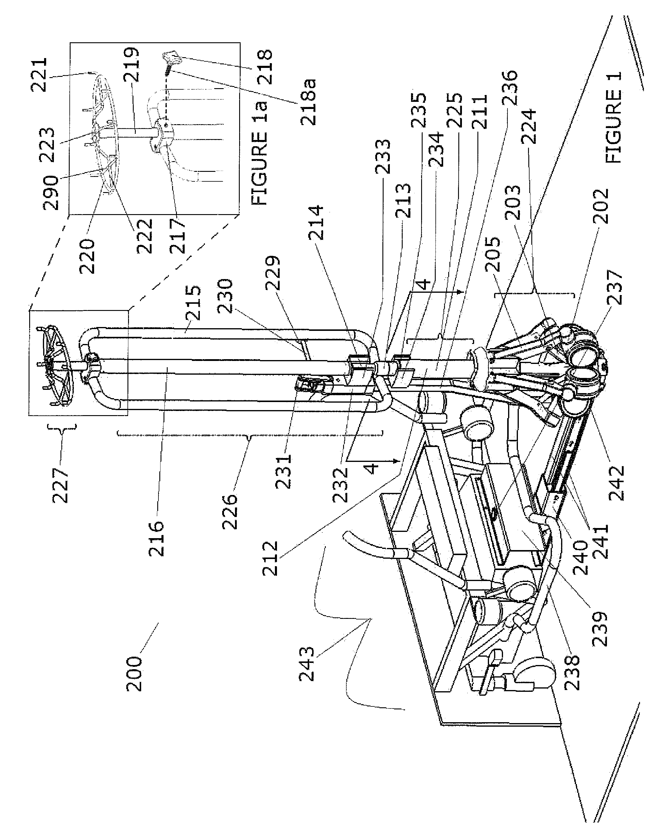
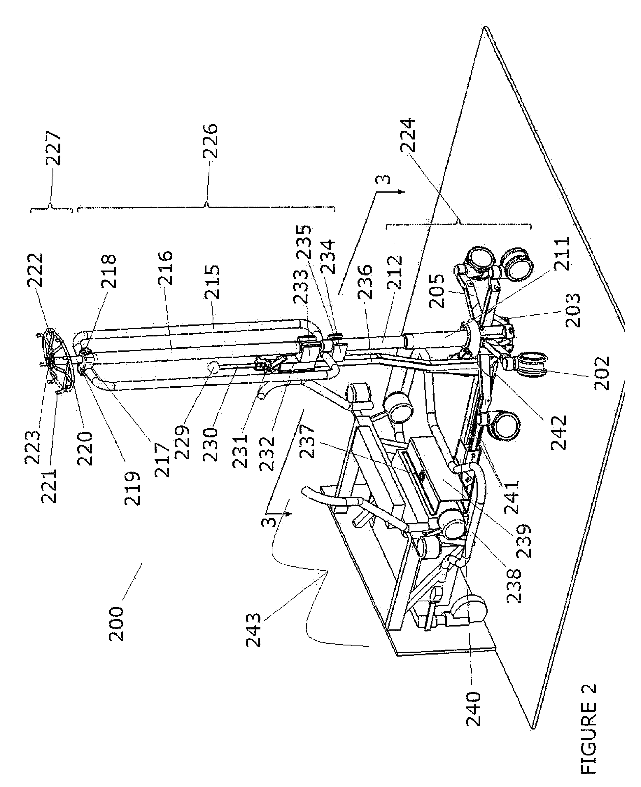
[0031]A common form of patient transport device comprises a patient holding apparatus used together with a mobile IV pole. Mobile IV pole design is constrained by two contradictory physical requirements. Mobile IV poles must simultaneously have a base sufficiently wide so that the poles are stable and do not easily fall over, and which are sufficiently narrow so that the IV pole may be positioned adjacent to a patient holding apparatus such as a wheelchair, wheeled bed, stretcher, gurney, or the like. Lack of attention to either of these two design requirements may be problematic tendering the IV pole in-operable. An IV pole with a narrow base may be unstable and potentially fall over, which may either pull out an IV lead from a patient or cause other physical injury. In addition, the tipping over of an IV pole may result in the bag or pumps being positioned below the patient, resulting in poor or non-transfusion of needed fluids into the patient. Alternatively an IV pole having a b...


PUM


Abstract

A patient transporting device having a mobile IV pole comprising a wheeled base, a mast, and a gas spring. Actuating the gas spring retracts the base with little or no effort on the part of a user. With the base retracted the IV pole can be positioned for engagement to a bed, gurney, or wheelchair. The IV pole may be releasably attached to one or more supporting mounts on the bed, gurney, or wheelchair to take the weight off of the wheeled base. This weight relief allows for easy retraction of the base by the gas spring. The supporting mounts can be pulled close to the bed, gurney, or wheelchair by biasing mechanism.

Description

CROSS-REFERENCE TO RELATED APPLICATIONS[0001]Not ApplicableSTATEMENT REGARDING FEDERALLY SPONSORED RESEARCH[0002]Not ApplicableBACKGROUND OF THE INVENTION[0003]1. Field of the Invention[0004]In some embodiments this invention relates to an improved IV pole, its manufacture, and methods of use. More particularly some embodiments relate to intravenous poles with transformable base widths to better facilitate the transport of patients.[0005]2. Description of the Related Art[0006]For many years, patients needing intravenous fluid transfusions have been able to be moved by a patient transportation apparatus such as a wheelchair, wheeled bed, stretcher, gurney, or the like while receiving such transfusions by the use of mobile IV poles. These IV poles, however, suffer from a number of drawbacks.[0007]One unsatisfactory form of a mobile IV pole is a pole permanently attached to, and using out of, the patient transportation device such as that described in published US Patent Application 20...

Claims


Application Information

Patent Timeline
Patent Type & Authority Applications(United States)
IPC IPC(8): B60P1/02A47C21/00B62D33/08F16F9/02A63B55/60
CPCA61G7/0503A61M5/1415A61G2203/80
Inventor BLANKENSHIP, PETER B.BLANKENSHIP, SAMUEL A.NORMAN, BRENT G.
Owner SKYTRON CORP
Why Eureka
Try Eureka