
Method and Apparatus for Single Side Bilayer Formation

a bilayer and lipid technology, applied in cell components, instruments, material electrochemical variables, etc., can solve the problems of inability to utilize the application of apposition in systems where only one side of an aperture is accessible, ion channels in this region will have a tendency to produce anomalously low conductances, and the painting method is a manual process that requires considerable skill to achieve, so as to avoid the significant learning curve

Active Publication Date: 2009-06-04
ELECTRONICS BIOSCI
View PDF8 Cites 23 Cited by
  • Summary
  • Abstract
  • Description
  • Claims
  • Application Information

AI Technical Summary

Benefits of technology

[0020]Advantageously, the present apparatus and method avoids the significant learning curve associated with employing tip-dip and membrane painting techniques and provides a reliable means for forming lipid bilayers across an aperture when only one side of the aperture is accessible.

Problems solved by technology

However, apposition cannot be utilized in systems wherein only one side of an aperture is accessible, e.g., a glass nanopore membrane or an array of nanopores with individual readouts.
Ion channels in this region will have a tendency to produce anomalously low conductances due to the high impedance of the water layer between the supported lipid bilayer and the glass.
The painting method is a manual process that requires considerable skill to accomplish and does not lend itself to automation.
Additionally, the PLB formed by painting contains a large amount of solvent due to the nature of the process.
The microfluidic PLB formation method requires a large number of steps and has not been shown to work for apertures under 100 μm in diameter.
Currently, there is no available method to reliably and automatically form lipid bilayers across an aperture when only one side of the aperture is accessible.

Method used


Image

  • Method and Apparatus for Single Side Bilayer Formation
  • Method and Apparatus for Single Side Bilayer Formation
  • Method and Apparatus for Single Side Bilayer Formation

Examples


Embodiment Construction

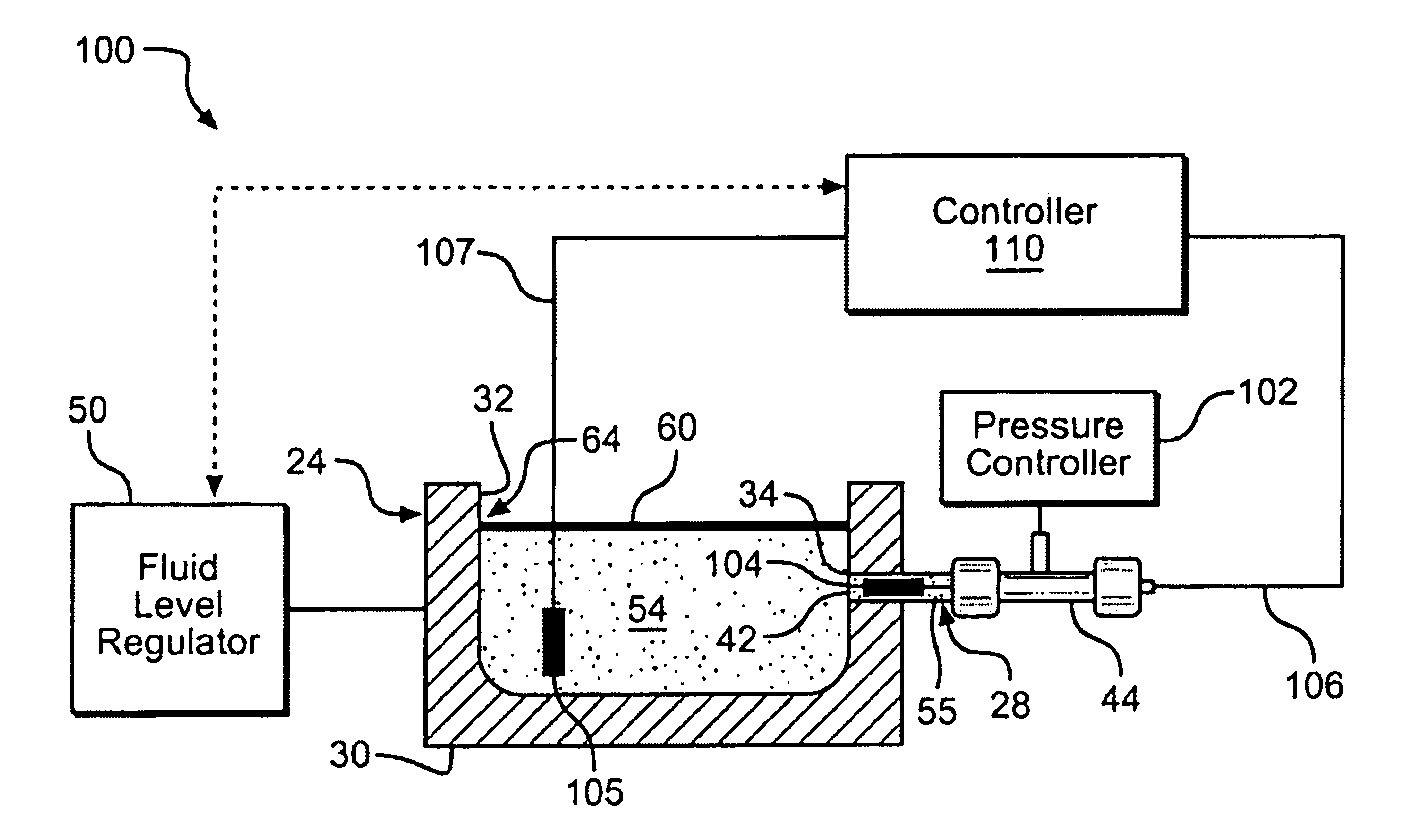
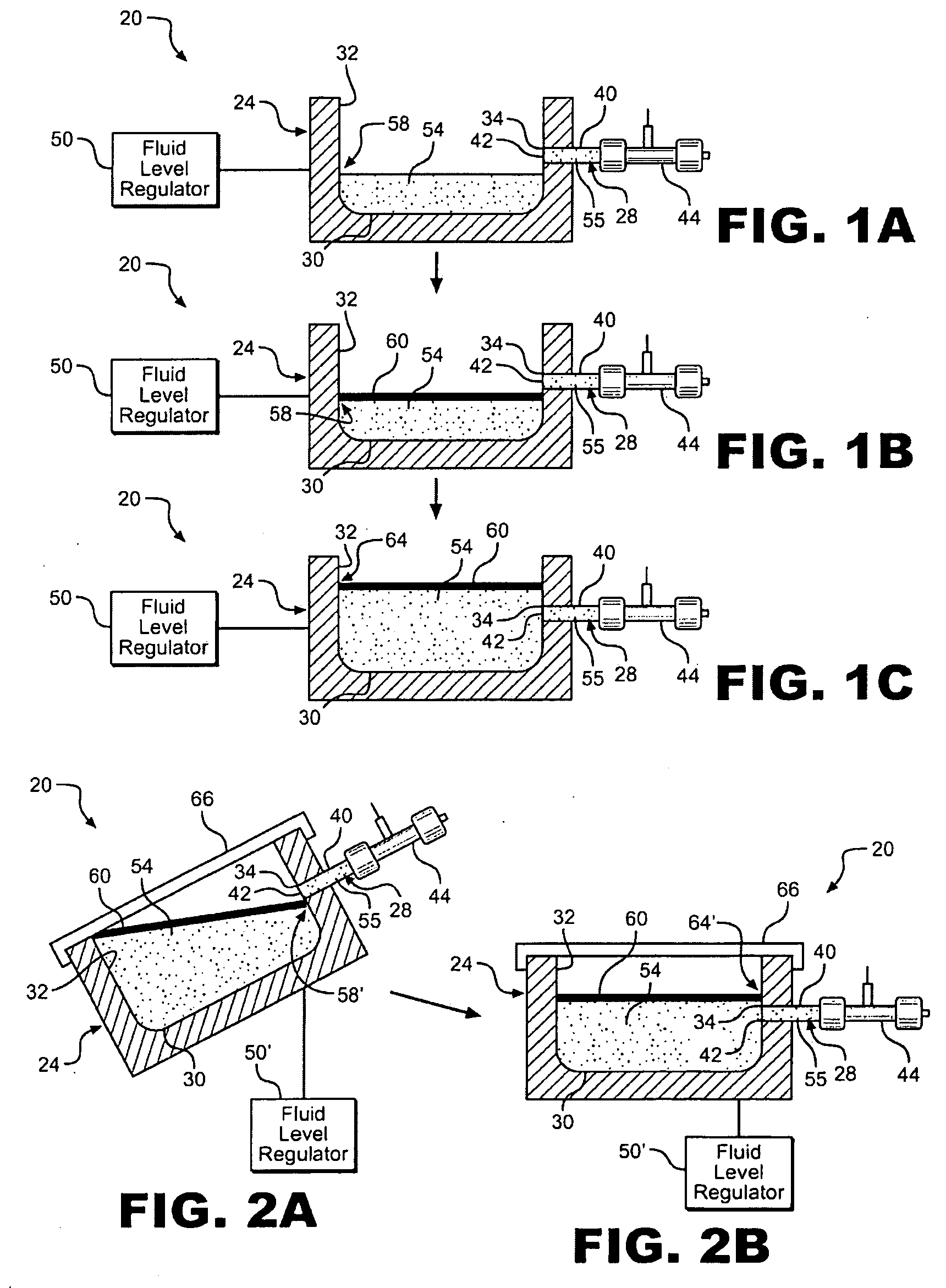
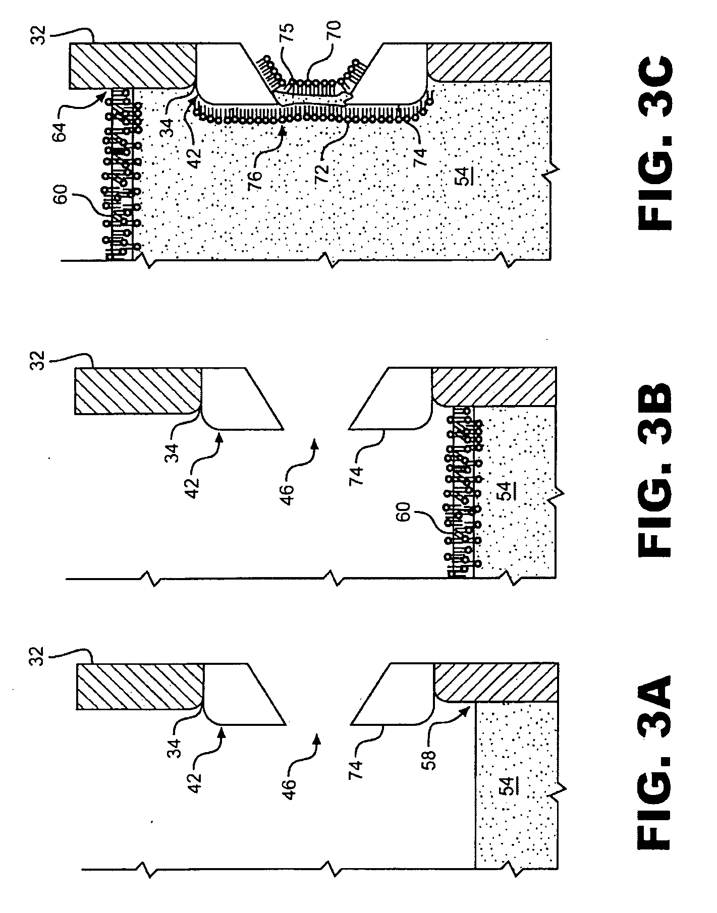
[0029]In general, the present invention is directed to a system and method for formation of planar lipid bilayers (PLBs) across nanometer and micron scale apertures, i.e. nanopores. With initial reference to FIGS. 1A-1C, a membrane forming apparatus of the present invention for use in single-side bilayer formation is generally indicated at 20. Membrane forming apparatus 20 includes a first fluid cell or chamber 24 adapted to retain fluid, and a second fluid chamber 28 adapted to retain fluid. First fluid chamber 24 includes a bottom wall 30 and at least one sidewall 32 including at least one aperture 34 therein through which second fluid chamber 28 is connected. In a preferred embodiment, first fluid chamber 24 is a 1.25 cm×3 cm×2 cm Teflon® cell having a total capacity of approximately 7.5 cm3. Second fluid chamber 28 also includes at least one sidewall 40 and a barrier wall 42 separating first fluid chamber 24 from second fluid chamber 28. In the preferred embodiment shown, second...


PUM


Abstract

An apparatus for single-sided bilayer formation includes a first fluid chamber including a sidewall and a second fluid chamber extending through the sidewall. A barrier wall separates the first and second fluid chambers and includes a nanopore therein across which a planar lipid bilayer (PLB) is formed. In use, an electrolyte is added to the first and second fluid chambers and a lipid / organic solvent mixture is added to the first fluid chamber to form a lipid / organic solvent layer. The electrolyte level within the first fluid chamber is adjusted such that the lipid layer is raised above the barrier wall and a PLB is formed. Electrolyte levels may be adjusted manually or utilizing a fluid level regulator with or without feedback control. Optionally, the apparatus may be in the form of a nanopore array. The apparatus may be incorporated into an ion channel sensing system wherein an electrical current through each PLB is separately recorded.

Description

CROSS-REFERENCE TO RELATED APPLICATIONS[0001]The present invention claims the benefit of U.S. Provisional Patent Application Ser. No. 60 / 991,542 entitled “Single Side Automated Bilayer Formation” filed Nov. 30, 2007.STATEMENT REGARDING FEDERALLY SPONSORED RESEARCH OR DEVELOPMENT[0002]The U.S. Government has a paid-up license in this invention and the right in limited circumstances to require the patent owner to license others on reasonable terms as provided for by the terms of Contract FA9550-06-C-006 awarded by the U.S. Air Force Office of Scientific Research.BACKGROUND OF THE INVENTION[0003]1. Field of the Invention[0004]The present invention pertains to the art of forming lipid bilayer membranes and, more particularly, to forming planar lipid bilayers across small orifices for use in ion channel sensing systems.[0005]2. Discussion of the Prior Art[0006]A planar lipid bilayer (PLB), also referred to as a black lipid membrane (BLM), is a membrane composed of lipids that spans an or...

Claims


Application Information

Patent Timeline
IPC IPC(8): B05D1/20G01R27/08B05C19/02H01M50/60H01M50/609H01M50/618
CPCH01B1/122G01N33/48721B82Y15/00H01M2/36Y02E60/10H01M50/60H01M50/609H01M50/618G01N27/30
Inventor ERVIN, ERIC N.BARRALL, GEOFFREY ALDEN
Owner ELECTRONICS BIOSCI
Learn More