Water conservation / hot water recirculation system utilizing timer and demand method

a water conservation and hot water recirculation technology, applied in domestic hot water supply systems, lighting and heating apparatuses, heating types, etc., can solve the problems of water initially coming out cold, substantial amount of residual cold water, and typically flowing directly into the drain

Inactive Publication Date: 2009-06-11
KERSHISNIK DONALD GREGORY
View PDF13 Cites 45 Cited by
  • Summary
  • Abstract
  • Description
  • Claims
  • Application Information

AI Technical Summary

Problems solved by technology

In most homes and other buildings, when a person turns on the hot water faucet of a sink, tub or shower, the water initially comes out cold, and he or she must wait for a period of time for the water to get hot.
During that waiting period, a substantial amount of residual cold water (that was sitting in the hot water pipes but cooled off by thermal radiation) typically flows directly into the drain and gets wasted.
However, pumping hot water around the loop at all times results in a loss of energy, particularly when, during much of the day or night, no hot water is being used.
The wireless method, which is generally powered

Method used


Image

  • Water conservation / hot water recirculation system utilizing timer and demand method
  • Water conservation / hot water recirculation system utilizing timer and demand method
  • Water conservation / hot water recirculation system utilizing timer and demand method

Examples


Embodiment Construction

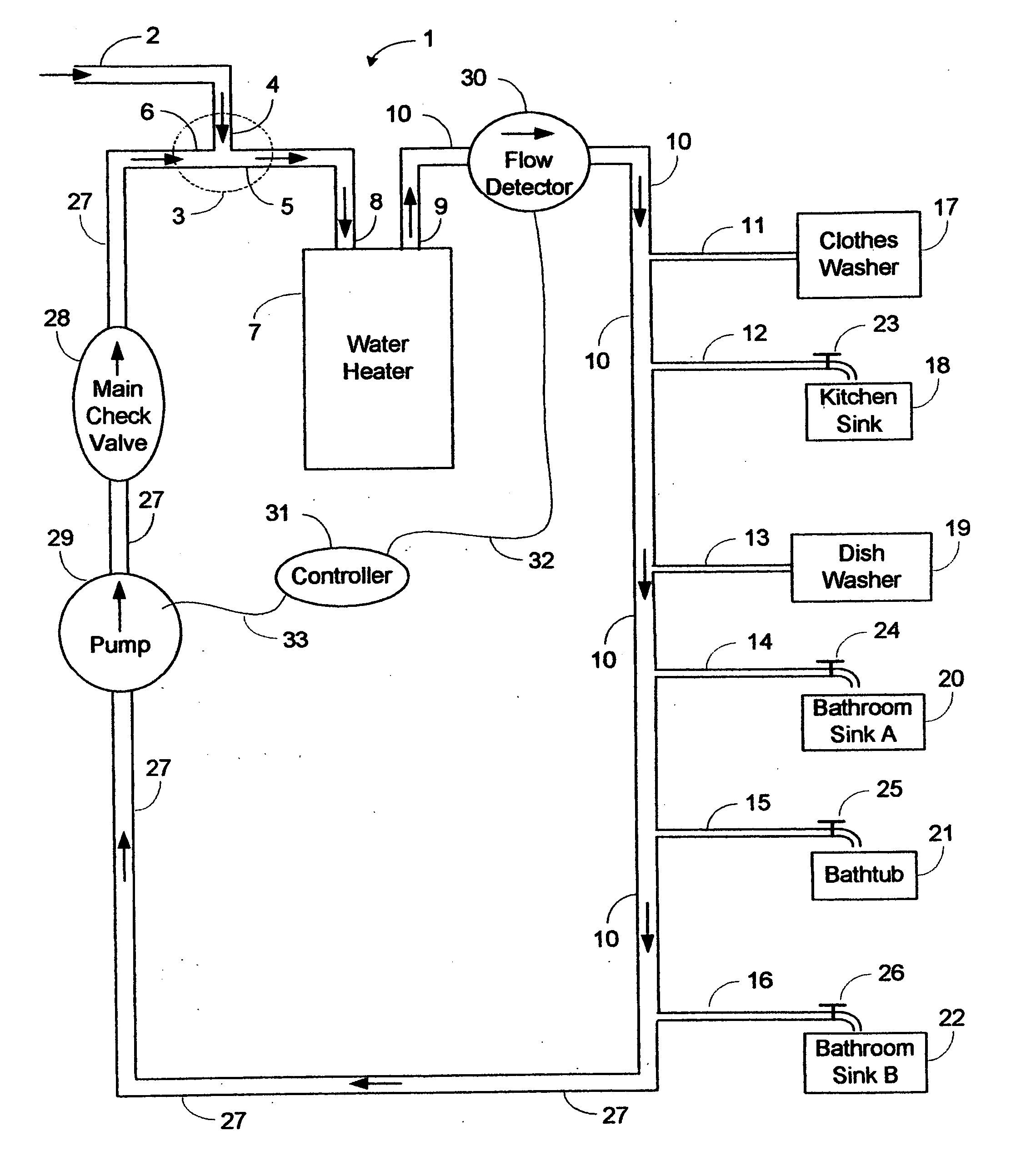
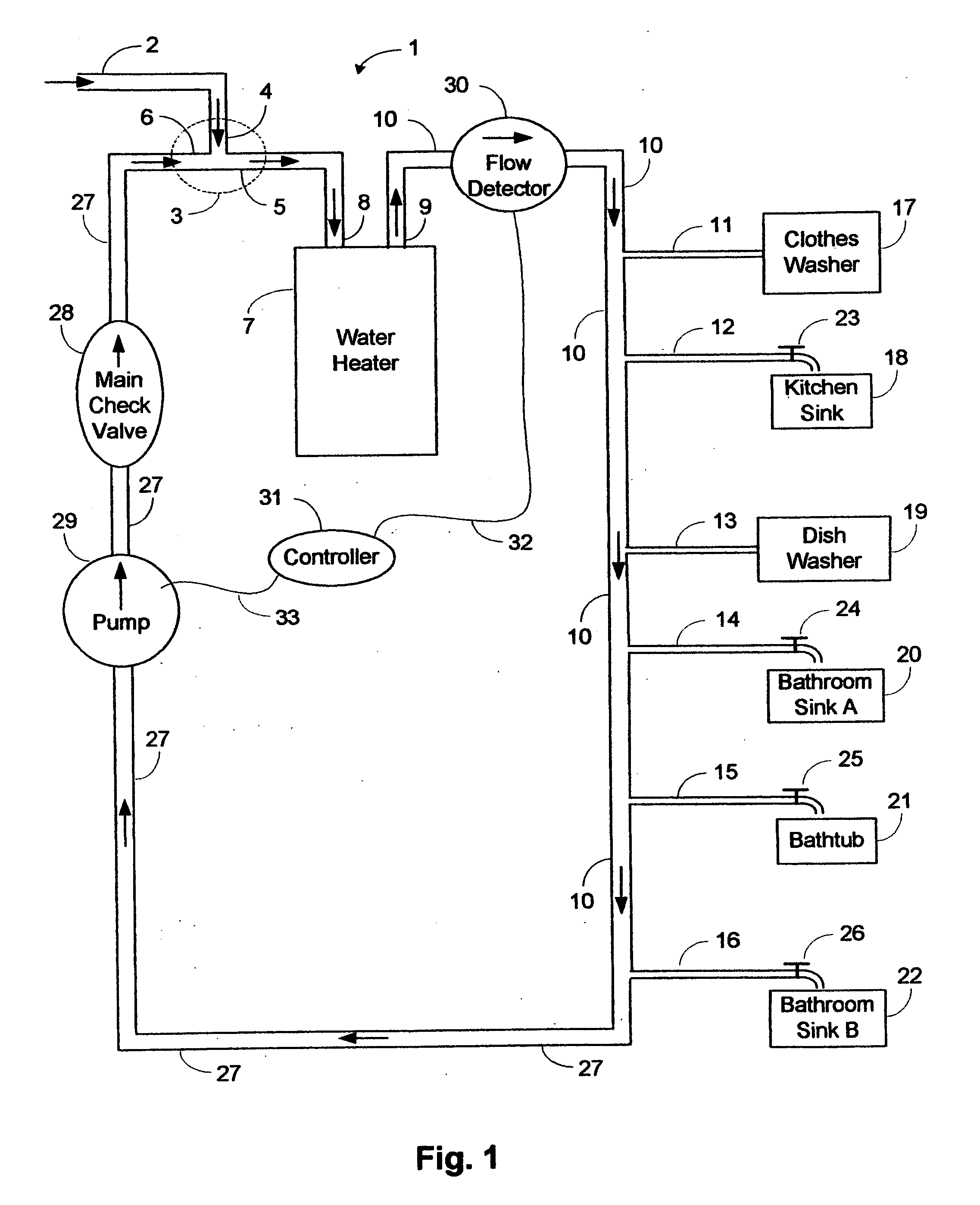
[0016]FIG. 1 shows the invention in its most general form. Cold water enters the system 1 through a source pipe 1, which connects to a main tee pipe 3. From there cold water flows out one port 5 of the main tee pipe to the inlet 8 of the water heater 7. Hot water flows out of the water heater 7 through its outlet 9 and into a hot main pipe 10, which feeds hot branch pipes 11-16 leading to various stations 17-22. The branch pipe at 11 is the nearest branch pipe to the water heater 7. Stations 17 and 19 are automatic stations. Stations 18 and 20-22 are manual stations, each having hot water faucets 23-26. Station 22 is the farthest manual station from the water heater 7. After reaching the farthest manual station 22, the hot main pipe 10 feed into a return pipe 27 which leads back to the main tee pipe 3, thereby completing the recirculation loop. A main check valve 28 is located on the return pipe 27 to prevent cold water from the source pipe 1 flowing through the return pipe 27 to th...


PUM


Abstract

In most homes today, when a person turns on a hot water faucet, he or she must wait for residual cold water to flow out of the hot water pipe as hot water travels from the water heater to the faucet. That residual cold water typically goes down the drain. In some buildings, recirculating hot water systems keep hot water flowing in a loop, thereby making hot water immediately available and eliminating the waste of residual hot water, but these systems waste energy from thermal radiation in the hot water pipes at times when no hot water is being utilized. The invention conserves both water and energy by controlling the recirculation of residual cold water by means of momentary activation of any hot water faucet, and also by programmed time-of-day intervals, whereupon the pump replaces the residual cold water with hot water and recirculates the residual cold water, and then turns off so as to avoid energy waste from running hot water through the loop at times it is not needed. The invention provides for fast installation of the pump, detector, and controller on the hot water outlet side of the water heater. It can be used in buildings that have separate hot water return pipes, and it can also be used in configurations where existing cold water pipes are used for the return of hot water.

Description

1. CROSS-REFERENCE TO RELATED APPLICATION[0001]This application refers back to Provisional Patent Application No. 60 / 954,998 filed on Aug. 7, 2007 by the same inventor, and the inventor requests the Aug. 7, 2007 filing date for purposes of the effectiveness of the non-provisional patent applied for herein.2. BACKGROUND OF THE INVENTION[0002]In most homes and other buildings, when a person turns on the hot water faucet of a sink, tub or shower, the water initially comes out cold, and he or she must wait for a period of time for the water to get hot. During that waiting period, a substantial amount of residual cold water (that was sitting in the hot water pipes but cooled off by thermal radiation) typically flows directly into the drain and gets wasted.[0003]Some buildings contain recirculating hot water systems wherein hot water is constantly flowing around a loop that passes within a short distance of the various hot water faucets. This eliminates most of the delay and, consequently...

Claims


Application Information

Patent Timeline
IPC IPC(8): F16L53/00
CPCE03B7/04F24D19/1051F24D17/0078E03B7/045Y02A20/411Y10T137/6416
Inventor KERSHISNIK, DONALD GREGORY
Owner KERSHISNIK DONALD GREGORY
Why Eureka
Try Eureka