Actuator

a technology of actuators and actuators, applied in the direction of elastic dampers, tractors, pedestrian/occupant safety arrangements, etc., can solve the problem of a large amount of bulky locking mechanisms

Inactive Publication Date: 2009-06-11
TOYODA GOSEI CO LTD
View PDF8 Cites 16 Cited by
  • Summary
  • Abstract
  • Description
  • Claims
  • Application Information

AI Technical Summary

Benefits of technology

[0017]In the actuator according to the aspect of the invention, when in operation, when the working fluid is introduced into the cylinder to fill it, the piston accommodated in the cylinder is pushed by the working fluid and then moves forwards together with the supporting rod. As this occurs, in the actuator of the invention, the working fluid flows into the accommodating portion which the locking pin is accommodated via the flow path provided in the piston at the same time as the piston is pushed by the working fluid, and the locking pin receives the pressure of the working fluid, whereby the piston moves forwards together with the supporting rod in such a state that a distal end face of the locking pin so pressed is kept in sliding contact with an inner circumferential surface of the cylinder at all times. Thereafter, in the event that the piston continues to move forwards until the locking pin accommodated in the piston is disposed in a position confronting the locking surface provided on the inner circumferential surface of the cylinder, due to the locking pin receiving the pressure of the working fluid which has been introduced into the accommodating portion of the locking pin via the flow path, the locking pin is momentarily caused to project from the accommodating portion and the distal end portion side of the locking pin comes to be locked on the locking surface. Then, since the locking pin is disposed in such a manner as to straddle between the accommodating portion and the locking surface with the proximal portion side accommodated in the accommodating portion in such a manner as be restricted from moving along the axial direction of the piston, the reverse movement of the supporting rod which has moved forwards can be restricted, whereby when the object to be protected is received by the receiving member after the supporting rod has moved forwards, the supporting rod is made to be plastically deformed so as to absorb the kinetic energy of the object to be protected. Furthermore, in the actuator of the invention, since the locking mechanism for restricting the reverse movement of the supporting rod which has moved forwards is made up of the locking pin accommodated within the piston and the locking surface formed on the inner circumferential surface side of the cylinder, the locking mechanism is provided in such a manner as not to project from the cylinder to the outside thereof, whereby the external shape of the actuator can be formed into the substantially circular cylindrical shape, and hence, the actuator can be made as compact as possible.
[0018]Consequently, the actuator of the invention can be fabricated compact even though the actuator includes the locking mechanism which can prevent the reverse movement of the supporting rod after the supporting rod has moved forwards.
[0019]In addition, in the actuator of the invention, since the locking pin is configured in such a manner as to be pushed outwards by making use of the working fluid, the necessity can be obviated of providing separately a drive source for actuating the locking mechanism, and hence, an increase in number of parts involved can be prevented while suppressing the complication of the configuration of the actuator.
[0024]Furthermore, in the actuator configured as described above, in the event that a return preventive device for preventing a return of the projecting locking pin is provided on a circumference of the locking pin in the accommodating portion, the locking pin which has projected from the accommodating portion can be prevented from returning to the accommodating portion side as a result of striking against the inner circumferential surface of the cylinder, whereby the projecting state of the locking pin can preferably maintained in a stable fashion.

Problems solved by technology

In the conventional actuator, however, since the locking mechanism is provided in such a manner as to project largely by an amount by which the locking piece itself and the biasing device are added from the cylinder in the direction which intersects the axis of the cylinder at right angles, the locking mechanism becomes largely bulky in the direction which intersects the axis of the cylinder at right angles, and thus, there has still been room for improvement in making compact the actuator itself.

Method used


Image

  • Actuator
  • Actuator
  • Actuator

Examples


Embodiment Construction

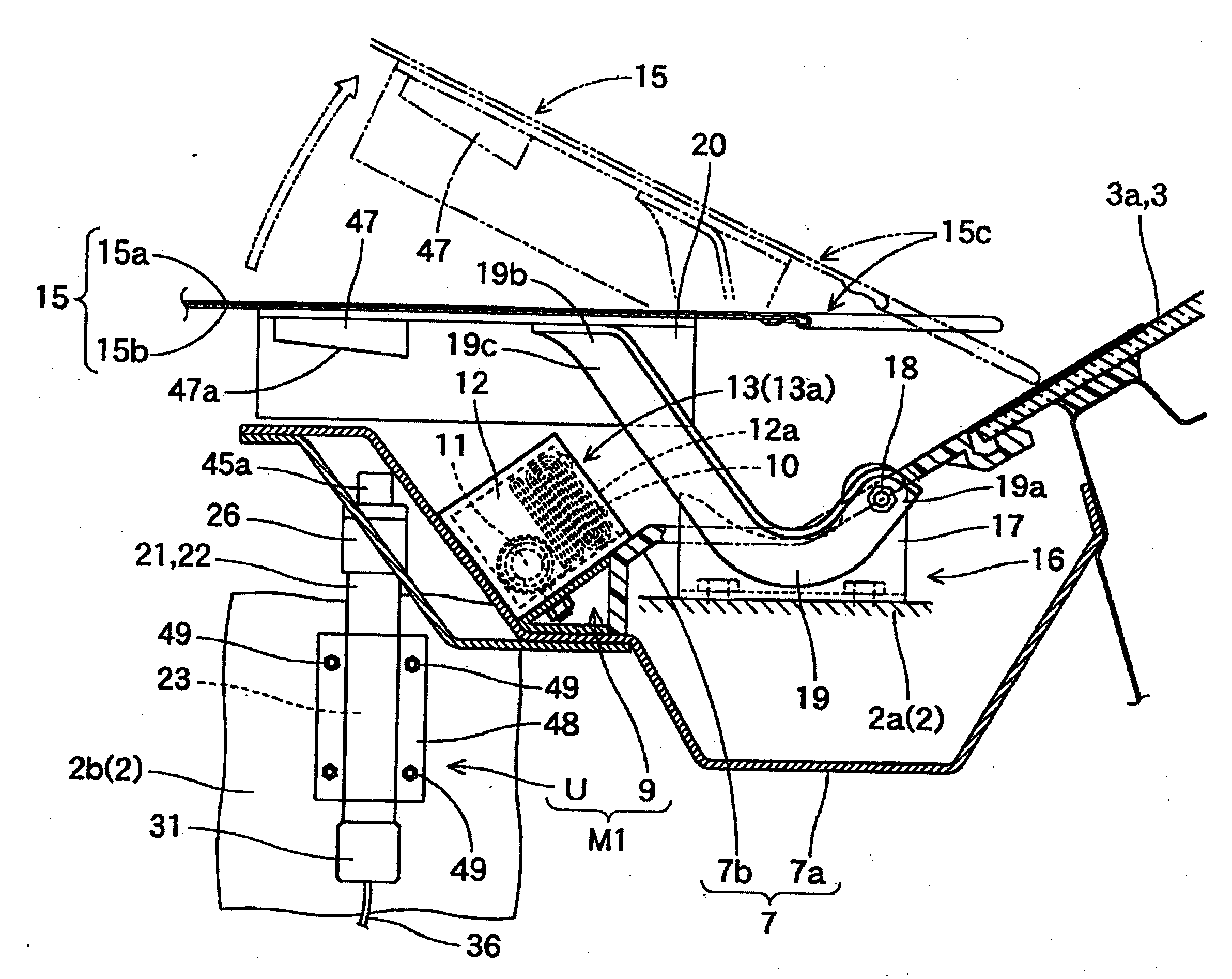
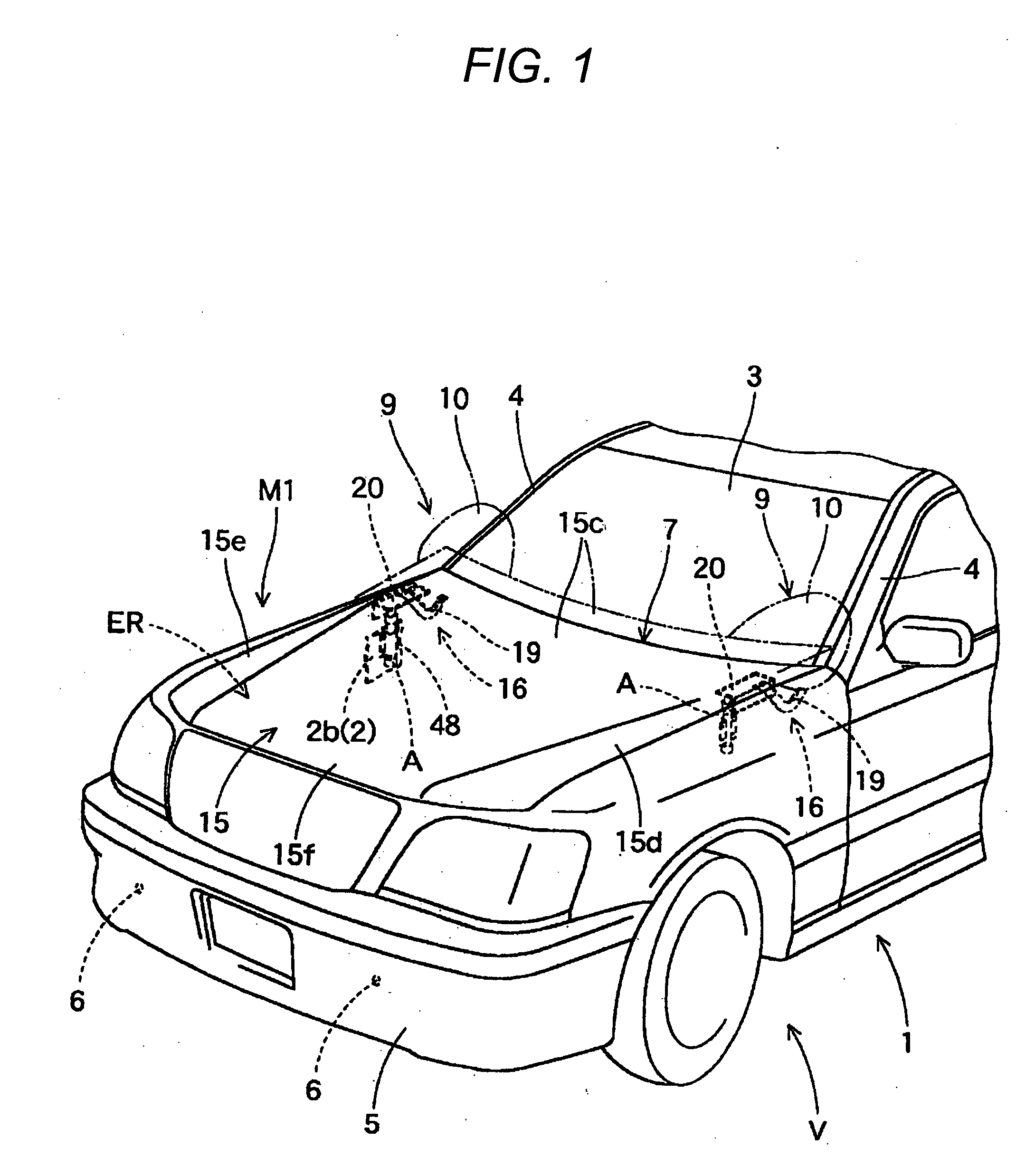
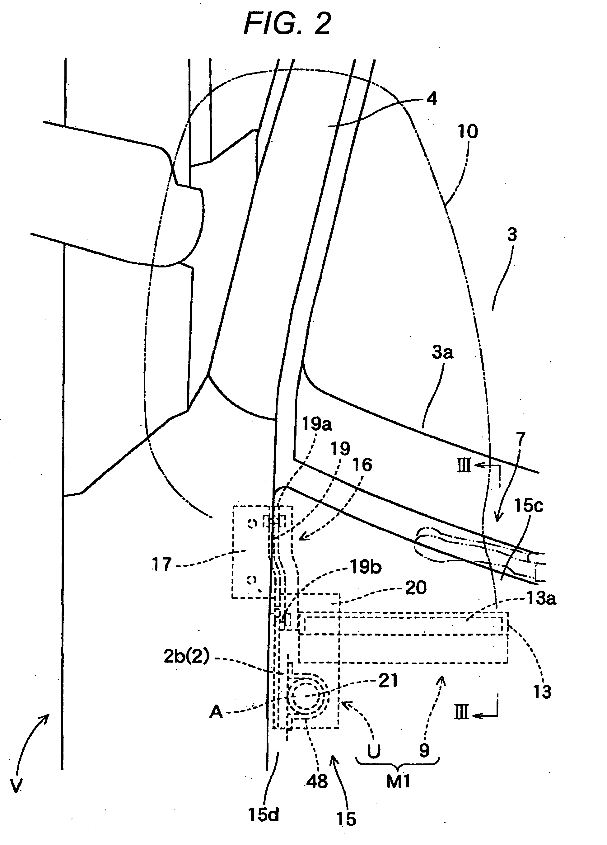
[0036]Hereinafter, an embodiment of the invention will be described based on the accompanying drawings. An actuator A according to an embodiment of the invention is, as is shown in FIGS. 1 to 3, an actuator for use in an uplift unit U in a pedestrian protection system which is an automotive safety system installed on a vehicle V. This uplift unit U is configured in such a manner as to uplift a rear end 15c of a hood panel 15 when the actuator A is put in operation. In addition, the actuator A of the embodiment is provided below a position lying in the vicinity of the rear end 15c of on the hood panel 15 of the vehicle V. The pedestrian protection system M is made up of the uplift units U for uplifting the rear end 15c of the hood panel 15 which acts as a receiving member for receiving a pedestrian and air bag units 9 each having an air bag 10 for protecting a pedestrian from a collision against a front pillar 4.

[0037]In addition, as is shown in FIG. 1, sensors 6 are provided on a fr...


PUM


Abstract

The invention provides an actuator A configured as an actuator in which a piston 38 disposed in a cylinder 21 is moved together with a supporting rod 45 connected to the piston 38 by introducing a working fluid G into the cylinder 21 and including a locking mechanism R for restricting a reverse movement of the supporting rod 45 which has moved forwards. The locking mechanism R includes a locking pin 43 adapted to project from an outer circumferential surface of the piston 38 which extends around an axis thereof, a flow path 40 which allows a working fluid G which flows into the cylinder 21 to flow, and a locking surface 25 for locking the locking pin 43 and is made to cause the locking pin 43 to project from the outer circumferential surface of the piston 38 by making use of the pressure of the working fluid G which is allowed to flow into an accommodating recessed portion 39 of the locking pin 43 via a flow path 40.

Description

BACKGROUND OF THE INVENTION[0001]1. Field of the Invention[0002]The present invention relates to an actuator for use in an automotive safety system and more particularly, for example, to an actuator which is used in a pedestrian protection system to lift up a hood panel which receives a pedestrian as an object to be protected.[0003]2. Description of the Related Art[0004]Conventionally, as an actuator for an automobile safety system installed on a vehicle, there has existed an actuator for raising a rear end side of a hood panel so that the hood panel can receive a pedestrian by itself by making use of energy absorption occurring when the hood panel is plastically deformed. Specifically, as a conventional actuator, there has been an actuator which is configured as a piston cylinder type actuator in which a piston disposed in a tubular cylinder is moved together with a supporting rod which is connected to the piston by introducing a working fluid into the cylinder and which has a lock...

Claims


Application Information

Patent Timeline
Patent Type & Authority Applications(United States)
IPC IPC(8): B60R21/34B60R21/36B60R21/38B62D25/08B62D25/10F15B15/14F15B15/26F16F7/12
CPCB60R21/38B60R21/36
Inventor HAYASHI, TAKEKIKITTE, HAJIMEAOKI, MASASHITAKAHASHI, HIROYUKI
Owner TOYODA GOSEI CO LTD
Why Eureka
Try Eureka