
Vacuum stabilized carry bag

a carry bag and vacuum stabilizer technology, applied in the field of carry bags, can solve the problems of discomfort for the bearer inability to tightly secure the contents of the carry bag, and exacerbate the problem of the carry bag

Inactive Publication Date: 2009-06-11
ROBINSON MARK AMIT
View PDF19 Cites 7 Cited by
  • Summary
  • Abstract
  • Description
  • Claims
  • Application Information

AI Technical Summary

Benefits of technology

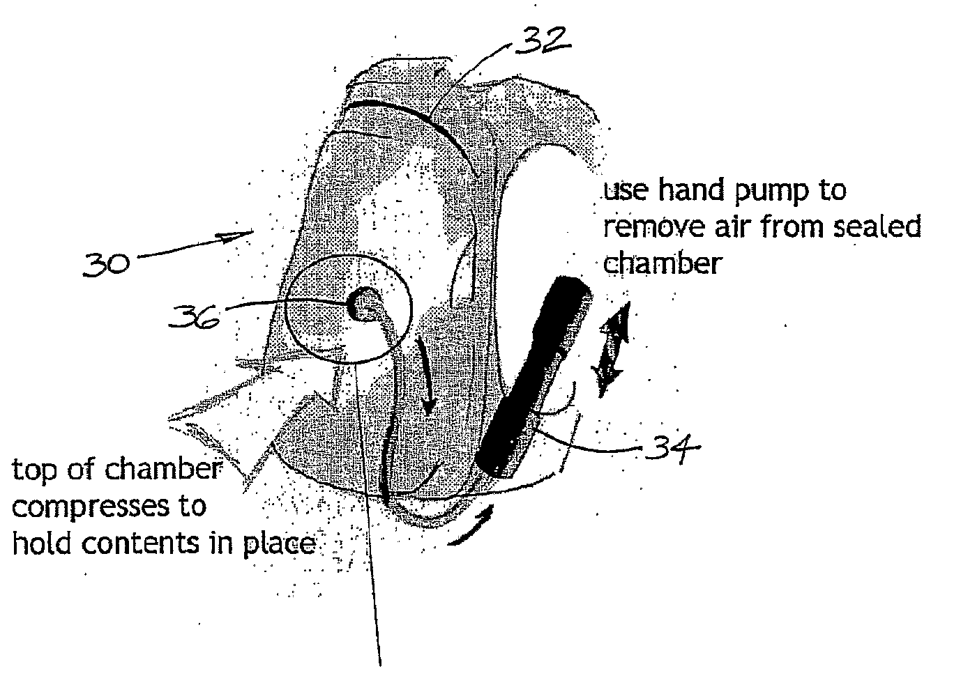
[0016]In a particularly preferred embodiment, the carry bag is a backpack having a rigid support wall adapted to abut against the back of a user, and including an inner bag having flexible walls and a sealable opening that allows contents to be packed and sealed within the inner bag and for a vacuum to be created and maintained when the opening is sealed. The inner bag is coupled to an air pump that, in use, evacuates air from the inner bag so as to cause the contents to be tightly secured against the rigid support wall, thereby reducing the volume of space occupied by the carry bag.

Problems solved by technology

However, there are numerous well known problems or limitations of such carry bags, one of which is the inability to tightly secure the carry bag contents.
For example, prolonged chaotic movement, as is the case with a runner's backpack, can cause damage to, and rearrangement of, its contents, leading to discomfort to the bearer of the carry bag.
The problem is exacerbated when the carry bag is not full, notwithstanding the careful and often time consuming packing of contents and the use of securing straps incorporated in some bags.
Another problem arises where the carry bag is oversized relative to its contents.
Where a carry bag is not packed to capacity or the contents are compressible, it is difficult to efficiently reduce the overall volume of the carry bag and its contents.
Some carry bags include a means of restricting volume by a strap or drawstring, but these devices are only partly effective in reducing volume and may malfunction during prolonged periods of use.
Waterproofing of carry bags is another problem that has not generally been addressed.
However, these carry bags are ineffective in heavy rain and cannot withstand immersion in water, and thus require, as a special precaution, the contents to be separately waterproofed before being packed into the carry bag.
None of the aforementioned prior art documents disclose the use of a vacuum created after packing and sealing contents into an airtight inner bag contained within a carry bag to reduce the volume of the inner bag for the purpose of compressing the contents against the carry bag and hence immobilize the contents.

Method used


Image

  • Vacuum stabilized carry bag
  • Vacuum stabilized carry bag
  • Vacuum stabilized carry bag

Examples


Embodiment Construction

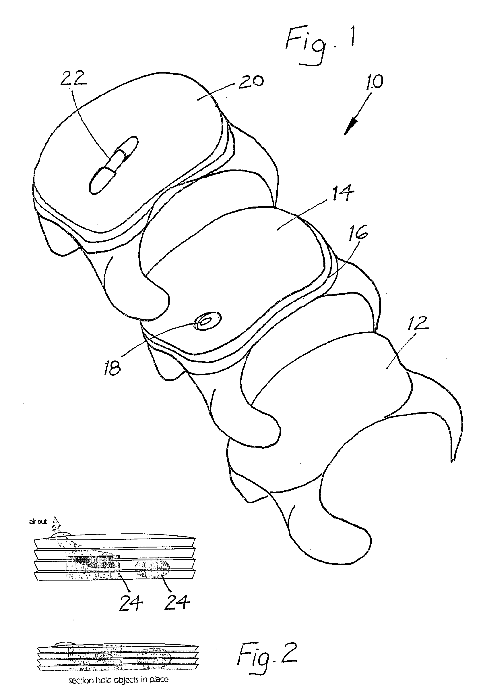
[0043]The carry bag 10 shown in FIG. 1 includes a base plate 12, an airtight bag 14 with a ziplock opening 16 and a suction pump coupling 18 attached to the airtight bag 14, and a protective outer sleeve 20 with a suction pump 22 attached thereto. Air can be evacuated from the bag 14 to compress any contents 24 therein against the base plate 12 in the manner as shown schematically in FIG. 2 by connecting the suction pump 22 to the coupling 18 and operating same.

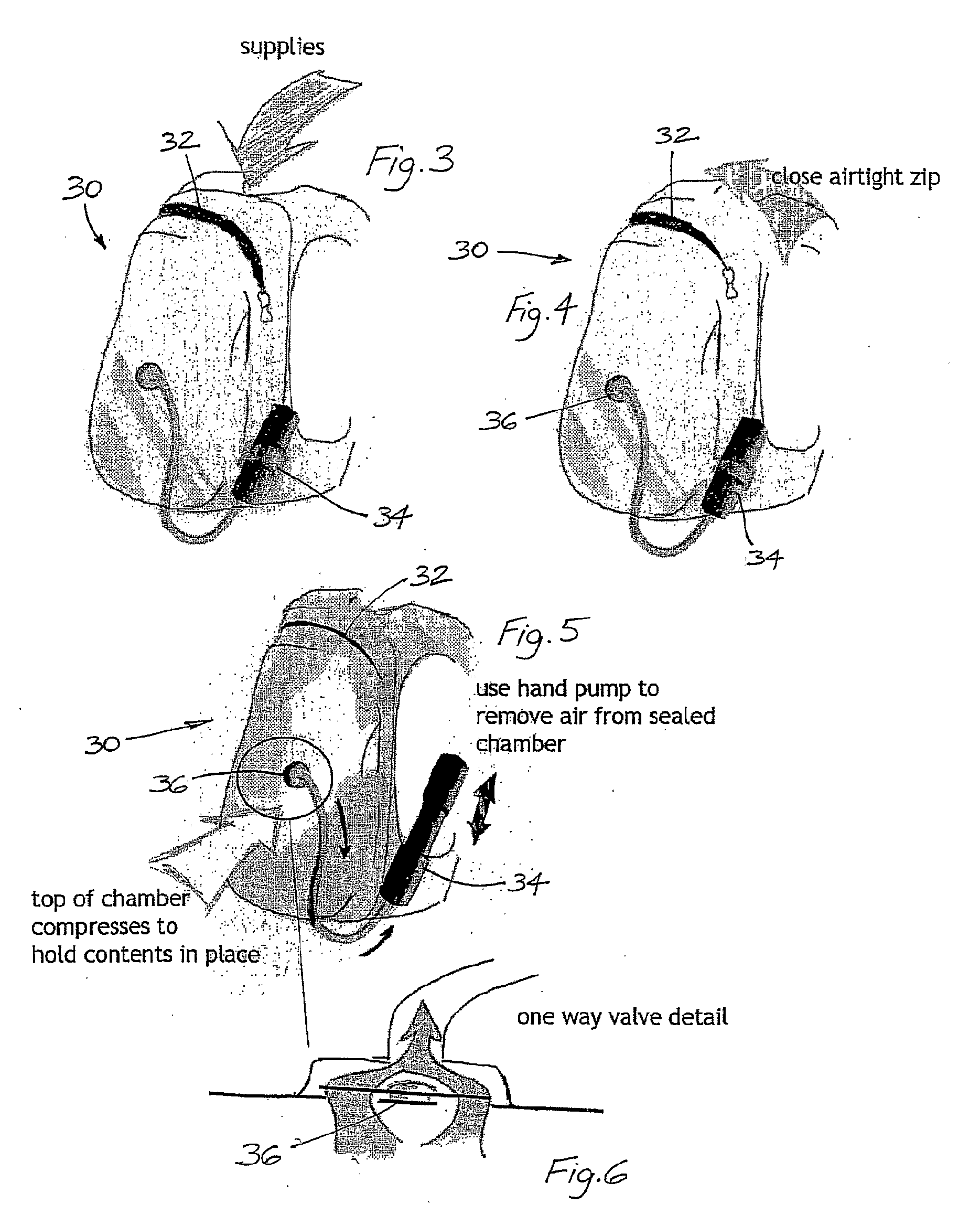
[0044]The carry bag 30 shown in FIGS. 3 to 5 is used, in a first stage, to receive contents through an outer sealable opening 32. The opening 32 is then closed to provide an airtight enclosure around the contents, and a hand pump 34 is then operated to evacuate air from the airtight enclosure. Flexible walls of the enclosure compress against the contents and hold them tightly in place. The one way valve 36 shown in FIG. 6 ensures that air cannot return into the enclosure during and after the operation of the hand pump 34.

[004...


PUM


Abstract

A carry bag (60) has flexible walls (69) defining an enclosure adapted to house contents of the bag. The enclosure has an opening (64) for receiving the contents therethrough, the opening being sealable for airtightness of the enclosure. There are also means, including a pump (68), for evacuating air from the enclosure so as to compress the walls against the contents to thereby restrain the contents from movement.

Description

FIELD OF THE INVENTION[0001]The present invention relates to improvements in carry bags and, in particular, to a carry bag that stabilizes its contents by the application of a vacuum. In an especially preferred form, the invention relates to a backpack which includes an inner airtight bag which may be evacuated of air by a suction device for compressing the bag tightly and sealably against the contents of the bag.BACKGROUND OF THE INVENTION[0002]For ease of understanding, the term “carry bag” as used in this specification embraces such items as backpacks, rucksacks, satchels, knapsacks, handbags, suitcases, riding or saddle bags, duffel bags, motorcycle panniers, and webbed carry pouches, such as those used by the military. All of these carry bags are designed to reliably envelope, and provide some degree of restricted access to, their contents, as well as provide a means of conveyance to the user, such as by handles, straps, buckles or latches.[0003]However, there are numerous well...

Claims


Application Information

Patent Timeline
IPC IPC(8): A45C13/00A45F3/04
CPCA45C13/021A45C2013/028A45F3/04A45F2003/166A45F4/12A45F2003/144A45F3/06
Inventor ROBINSON, MARK AMIT
Owner ROBINSON MARK AMIT
Learn More