Supercharge Your Innovation With Domain-Expert AI Agents!

Phase change memory

a phase change memory and memory technology, applied in the field of memories, can solve the problems of difficult production of isolated phase change elements and affect the quality of conventional phase change memories

Inactive Publication Date: 2009-06-11
POWERCHIP SEMICON CORP
View PDF2 Cites 2 Cited by
  • Summary
  • Abstract
  • Description
  • Claims
  • Application Information

AI Technical Summary

Benefits of technology

[0008]The invention provides phase change memories. The phase change memory comprises a top electrode, a phase change element, a plurality of via holes, four heaters, four bottom electrodes, and four transistors. The via holes are allocated between the top electrode and the phase change element. The heaters aim at different regions of the phase change element. The phase change regions aimed by the heaters form a 2×2 storage array. The bottom electrodes, the heaters and the transistors have a one-to-one relationship. The bottom electrodes are coupled to their corresponding heaters and transmit signals into their corresponding heaters. Each of the transistors comprises a first terminal, ...

Problems solved by technology

Thus, the space between the phase change elements is very narrow and it is difficult to produce the isolated phase change elements.
In addition, because the size of the isolated phase change elements is too small, the quality of the conventional phase change memory is also affected by plasma-induced damages occurring during the etching process.

Method used


Image

  • Phase change memory
  • Phase change memory
  • Phase change memory

Examples


Embodiment Construction

[0015]The following description shows some embodiments carrying out the invention. This description is made for the purpose of illustrating the general principles of the invention and should not be taken in a limiting sense. The scope of the invention is best determined by reference to the appended claims.

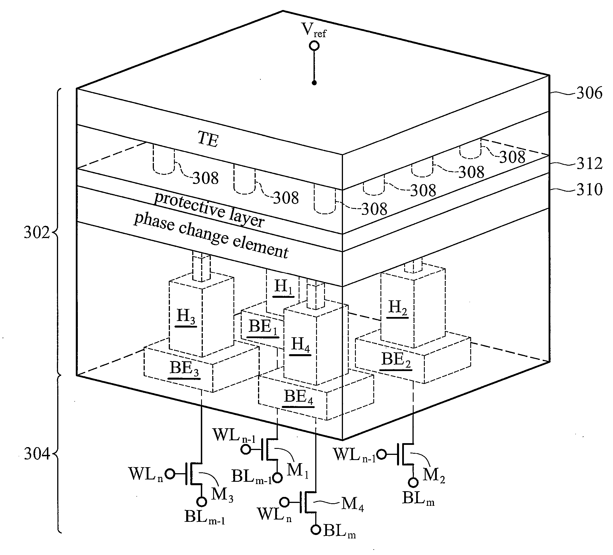
[0016]FIG. 2 illustrates an embodiment of the phase change memory of the invention, comprising three storage cells controlled by a word line WLn and bit lines BLm−1, BLm and BLm+1. FIG. 2 comprises two parts: one is a phase change device 202 of the phase change memory, which is shown by a cross-section view; and the other part is a circuit 204 comprising transistors controlling the phase change device. The phase change memory shown in FIG. 2 comprises a top electrode 206, a plurality of via holes 208, a phase change element 210, a plurality of heaters 212, a plurality of bottom electrodes 214 and a plurality of transistors 216. The via holes 208 are allocated between the top electr...


PUM


Abstract

Phase change memories comprising a top electrode, a phase change element, a plurality of via holes allocated between the top electrode and the phase change element, at least four heaters aiming at different regions of the phase change element, and a plurality of bottom electrodes and transistors corresponding to the heaters. The bottom electrodes are respectively coupled to the heaters. Regarding the transistors, their first terminals are respectively coupled to the bottom electrodes, their control terminals are used for coupling to word lines, and their second terminals are used for coupling to bit lines. In an embodiment with four heaters, the regions the heaters aimed at the phase change element form a 2×2 storage array.

Description

CROSS REFERENCE TO RELATED APPLICATIONS[0001]This application claims priority of Taiwan Patent Application No. 96147212, filed on Dec. 11, 2007, the entirety of which is incorporated by reference herein.BACKGROUND OF THE INVENTION[0002]1. Field of the Invention[0003]The present invention relates to memories and particularly relates to Phase Change Memories (PCMs).[0004]2. Description of the Related Art[0005]FIG. 1 illustrates a conventional phase change memory, comprising three storage cells controlled by a word line WLn and bit lines BLm−1, BLm and BLm+1. The figure comprises two parts: one is symbolized by 102, which is the cross-section view of a phase change device of the phase change memory; and the other part is a circuit 104 comprising transistors controlling the phase change device 102. To read / write the storage cell corresponding to the word line WLn and the bit line BLm−1, the conventional technique provides a top electrode 106, a via hole 108, a protective layer 110, a ph...

Claims


Application Information

Patent Timeline
IPC IPC(8): H01L47/00
CPCG11C13/0004H01L27/2436H01L27/2472H01L45/144H01L45/1233H01L45/126H01L45/06H10B63/30H10B63/82H10N70/8413H10N70/231H10N70/826H10N70/8828
Inventor HUANG, MING-JENGLIN, YUNG-FA
Owner POWERCHIP SEMICON CORP
Features
  • R&D
  • Intellectual Property
  • Life Sciences
  • Materials
  • Tech Scout
  • Unparalleled Data Quality
  • Higher Quality Content
  • 60% Fewer Hallucinations
Learn More