Pin site wound protection system

a wound protection system and pin technology, applied in the field of medical devices, can solve the problems of psychological trauma in some patients, prior art pin site wound protection systems do not allow convenient dressing change, etc., and achieve the effect of reducing the time required for dressing chang

Inactive Publication Date: 2009-06-11
LEE HARRY +2
View PDF9 Cites 20 Cited by
  • Summary
  • Abstract
  • Description
  • Claims
  • Application Information

AI Technical Summary

Benefits of technology

[0005]The present invention is an improved disposable pin site wound protection system for covering the entry or exit site of a surgical pin such as a halo pin, external fixation pin, traction pin, or surgical wire, wherein the system substantially reduces the time required to change a dressing at a pin site wound. The invention comprises a sponge and clip, both of which are designed to be attached to a pin adjacent a wound. The clip, when compressed, crosses the legs of the clip and when released will attach to the full-range of external fixation pins and wires. This reverse action of the clip, opening when compressed and closing when released, is a self-closing and self-holding clip that can be applied and removed with one hand. Unlike existing devices, the clip allows pressure against the sponge for immediate post-operative cessation of bleeding at the pin site and can be backed off to vary the pressure according to the stage of healing. The sponge is preferably cylindrical or hemispherical in shape, and may include a spiral cut to resist accidental displacement from the pin. The sponge may be of various medical grade materials and may or may not be impregnated with antiseptic or other anti-pathogenic agents.

Problems solved by technology

Unfortunately, prior art pin site wound protection systems do not allow convenient changing of the wound dressings and are not designed for single-handed application by poly-trauma patients.
Further, the appearance of the wound where the surgical pin enters or exits the skin is unsightly, causing psychological trauma in some patients, especially children.

Method used


Image

  • Pin site wound protection system
  • Pin site wound protection system
  • Pin site wound protection system

Examples


Embodiment Construction

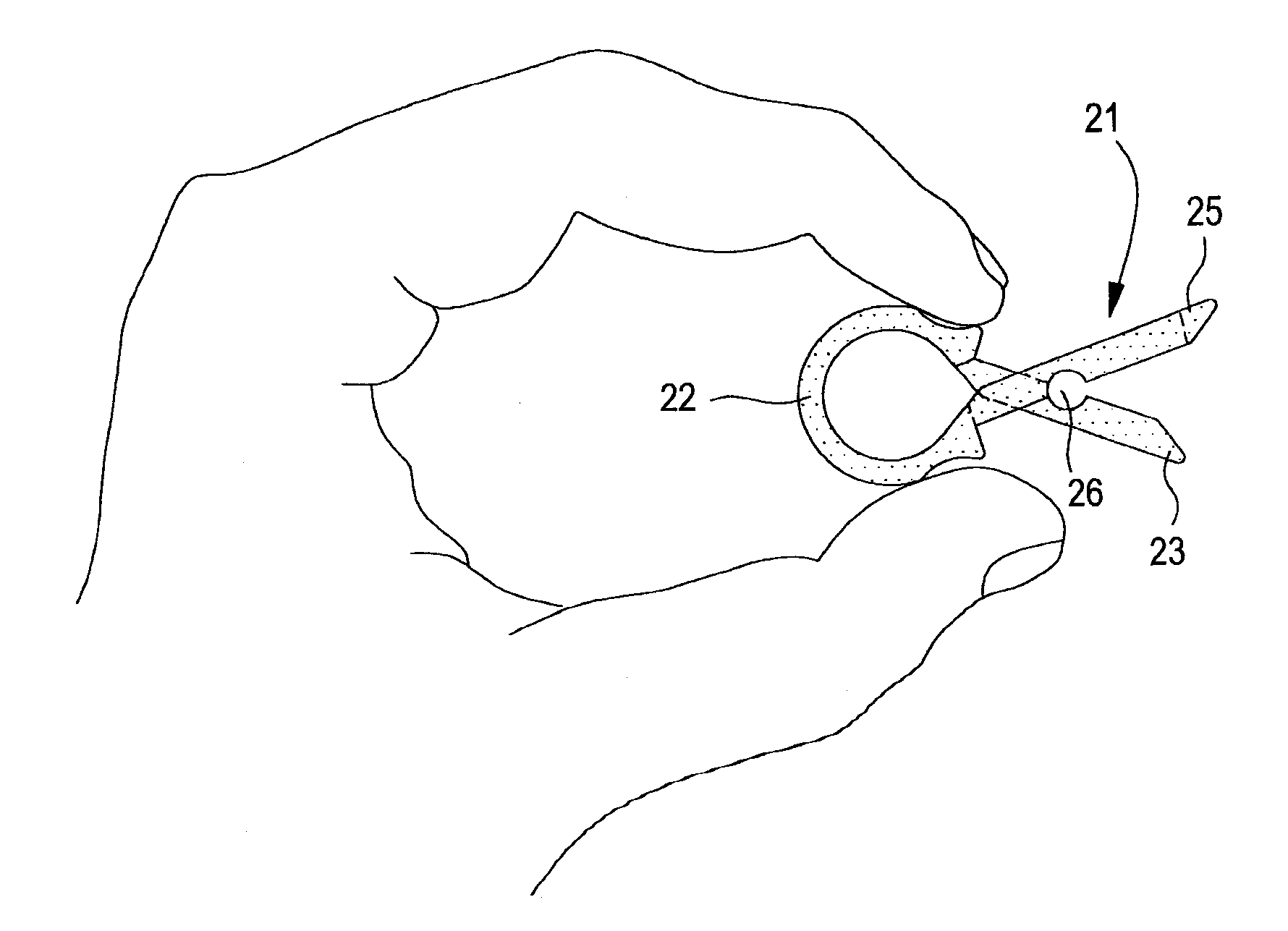
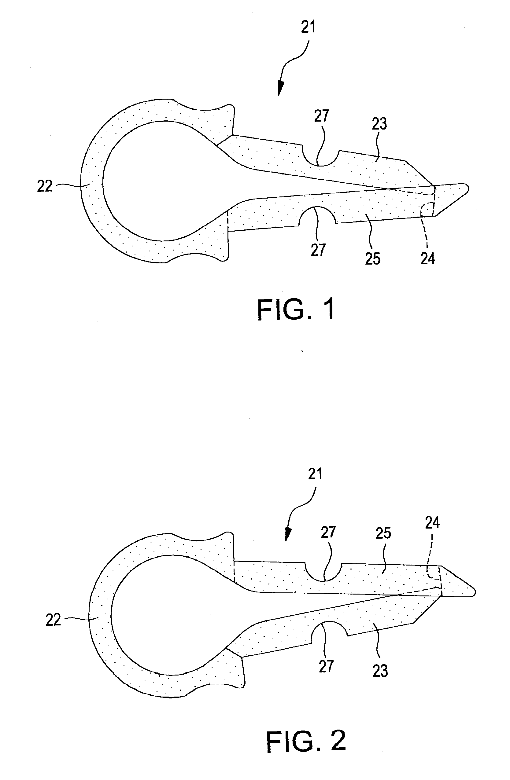
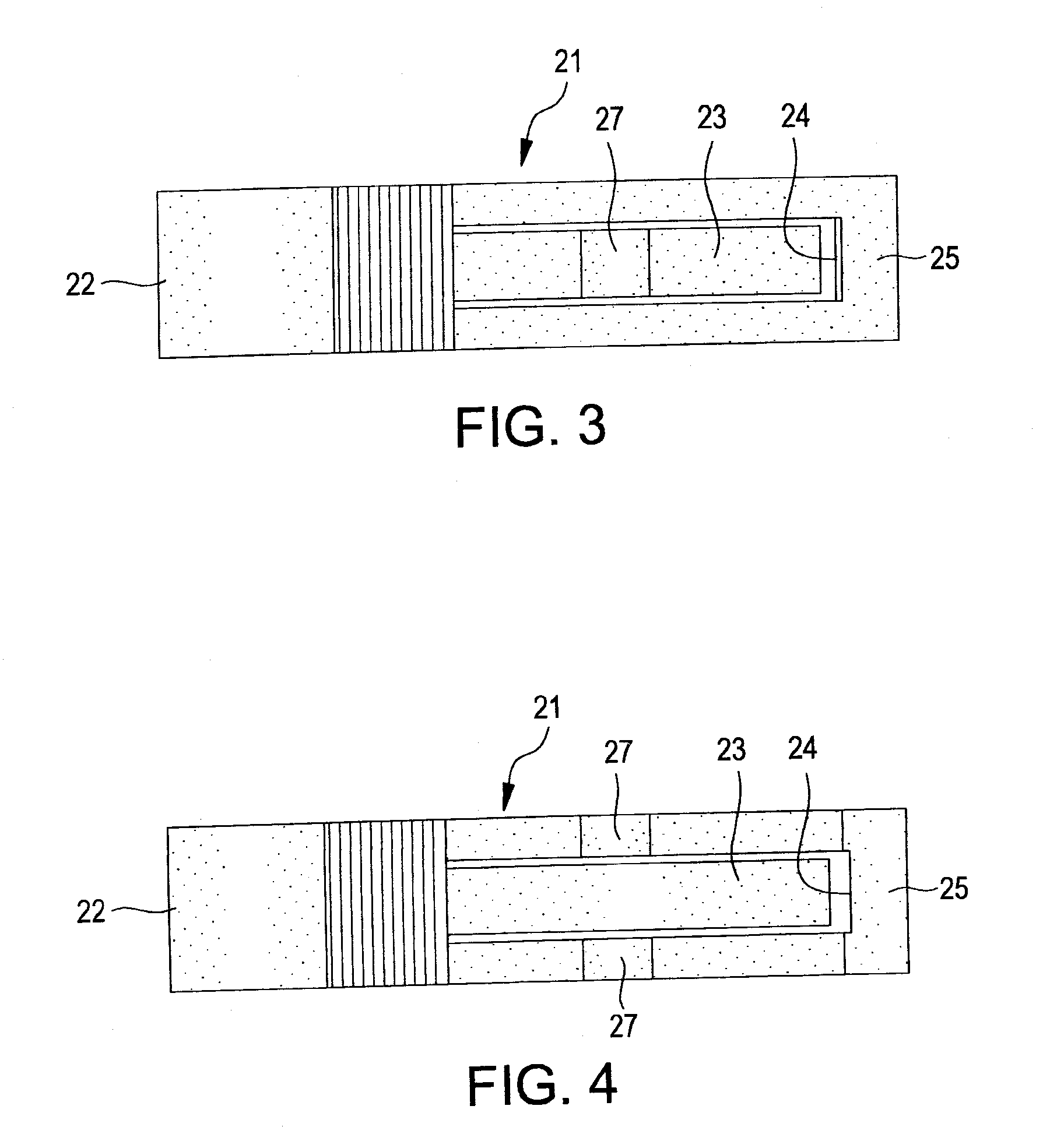
[0018]This application claims priority to U.S. Provisional Patent Application No. 60 / 701,346, filed Jul. 21, 2005, the disclosure of which is incorporated herein by reference. The present invention comprises a sponge 11 and a clip 21, both of which are designed to be attached to a pin 15 adjacent a wound. The sponge 11 may have any prior art design, such as a cylindrical design (FIGS. 9A-9B), or the sponge 11 may be hemispherical (FIGS. 10A-10B). A hemispherical sponge allows pressure to be applied to the pin exit site by the spherical side of the sponge or, alternatively, the sponge could be turned around so the flat side would disperse pressure over a wider area. The sponge 11 may include a spiral cut 12, shown in the hemispherical sponge in FIGS. 10A-10B, to resist accidental displacement from the pin 15. To secure a spiral cut sponge, the sponge is twisted onto the pin 15 until the pin 15 is within the central axial opening 13 through the sponge. The spiral cut may be in other s...


PUM


Abstract

An improved disposable pin site wound protection system for covering the entry or exit site of a surgical pin, wherein the system substantially reduces the time required to change a dressing at a pin site wound. The invention comprises a sponge (11) and clip (21), both of which are designed to be attached to a pin (15) adjacent a wound. The clip (21), when compressed, crosses the legs (23, 25) of the clip and when released will attach to the full-range of external fixation pins and wires. This reverse action of the clip, opening when compressed and closing when released, is a self-closing and self-holding clip that can be applied and removed with one hand. The sponge (11) is preferably cylindrical or hemispherical in shape, and may include a spiral cut (12) to resist accidental displacement from the pin.

Description

TECHNICAL FIELD[0001]The present invention relates to medical devices, and more particularly, to a surgical dressing for covering the entry or exit site of a surgical pin or surgical wire.BACKGROUND ART[0002]Fixation of severely broken bones frequently requires the use of a plurality of surgical pins, wires, or similar implements inserted radially into the injured limb, with the distal ends protruding outwardly through a patient's skin. Such surgical implements, referred to collectively herein as pins, may be integral components of complex fixation systems, and may remain in position for several days, weeks, or even months, depending upon the severity of the injury and other factors. Examples of prior art pin site wound protection systems are described in U.S. Pat. Nos. 4,943,293 and 5,360,020, the disclosures of which are incorporated herein by reference.[0003]In order to minimize the risk of infection, it is essential that the wound dressings be regularly changed. Unfortunately, p...

Claims


Application Information

Patent Timeline
Patent Type & Authority Applications(United States)
IPC IPC(8): A61B17/58
CPCA61B17/60A61F15/006A61B17/84
Inventor LEE, HARRYREARDON, JOSHUAPALEY, DROR
Owner LEE HARRY
Why Eureka
Try Eureka