
Roofer's kneepads

Inactive Publication Date: 2009-06-18
VISIONARY TECH
View PDF5 Cites 18 Cited by
  • Summary
  • Abstract
  • Description
  • Claims
  • Application Information

AI Technical Summary

Benefits of technology

[0009]It is an object of the present invention to overcome the deficiencies noted in the prior art concerning kneepads, particularly as they pertain to working on an inclined roof. It is another object of the present invention to provide kneepads that reduce or eliminate pressure on its user's feet.
[0010]It is another object of the present invention to provide shin wedges that reduce or eliminate shear forces on a user's body when working on an inclined surface.
[0011]It is another object of the present invention to increase the safety of workers on steeply inclined surfaces by increasing their frictional contact onto it.
[0014]The user of the present invention is more comfortable because the effect of the incline is substantially eliminated, and the user feels as if he is kneeling on a nearly horizontal surface. This reduces strain on the back, ankle, and toes. The shearing force on the skin of the user, whether felt through clothing or directly on the skin, is completely eliminated if the wedge angle is the same as the pitch of the roof. More generally, that shearing force is at least substantially reduced in proportion to how closely the wedge angle equals the pitch of the roof.
[0015]Furthermore, the user is safer because the contact with the roof is the entire bottom surface of the shin wedge, which can easily be made much larger than the combined area of a person's kneefronts and toes, even if the kneefront is supplemented by the sort of kneepad existing in the prior art.
[0016]The force of gravity is vertical and in the customary notation of physics is m*g, where m is the mass (in this case, of the worker plus the shin wedge) and g is the acceleration of gravity. When the mass is resting on an inclined plane (such as a roof) having pitch angle P, measured from horizontal, the force of gravity can be resolved into m*g*sin(P) pointing along the roof, and m*g*cos(P) perpendicular to the roof. The vector m*g*cos(P) is not relevant to the following discussion. It is the force vector m*g*sin(P) that causes the worker to slide down the roof. The frictional force that resists sliding of the shin wedge is a vector pointing along the roof in the opposite direction to m*g*sin(P). Undesired sliding occurs when the force vector m*g*sin(P) exceeds the frictional force. As the value of P increases, sin(P) increases, and more frictional force is needed. The wedge angle does not come into this calculation directly. The only way to increase frictional force is to increase the area of the shin wedge in contact with the roof, or to enhance its frictional properties. A larger wedge angle for a given length of the shin wedge along the user's shin will result in a longer surface, that being the hypotenuse of the triangle in which the length along the shin is adjacent to the wedge angle. Therefore, the wedge angle comes indirectly into the calculations for resisting sliding, by increasing the area providing the friction. The sine for P=45 degrees is approximately twice the sine for P=20 degrees, so the area of frictional contact, and the frictional force (although that also depends on the friction material) would be approximately double for a shin wedge with wedge angle 45 degrees compared to a shin wedge with wedge angle 20 degrees. No knee or shin protector in the prior art has this beneficial effect that increases safety of the user of the present invention.

Problems solved by technology

Kneeling to work on either a sloped surface such as a roof, or a horizontal surface such as a floor, presents an ergonomically challenging task that stresses a worker's legs and feet.
This unsupported leg geometry continuously strains a kneeling worker's ankle and toe muscles as they counterbalance fore and aft motions of the upper body, regardless of whether a task is being performed on a flat or inclined surface.
It also puts strain on the worker's back.
The shear force results in an unpleasant feeling, as the worker's skin, whether through clothing or not, stretches to stop sliding down the roof.
The strain on the back is also worse in this position.
In general, the prior art kneepads do not alleviate the foot muscle strain caused by unsupported shins, and none provide relief from the shear forces experienced when working on an inclined work surface.
This creates an uncomfortable, or uneasy feeling in the wearer, and undue pressure on the knee joint because there is no support directly under the thigh which is putting downward pressure on the knee joint.
Sveilich discloses one embodiment that joins the kneepad to the shin rest, at an articulated joint, which would be altogether quite long and massive and that is undesirable for the wearer when standing up while still wearing the device.

Method used


Image

  • Roofer's kneepads
  • Roofer's kneepads
  • Roofer's kneepads

Examples


Embodiment Construction

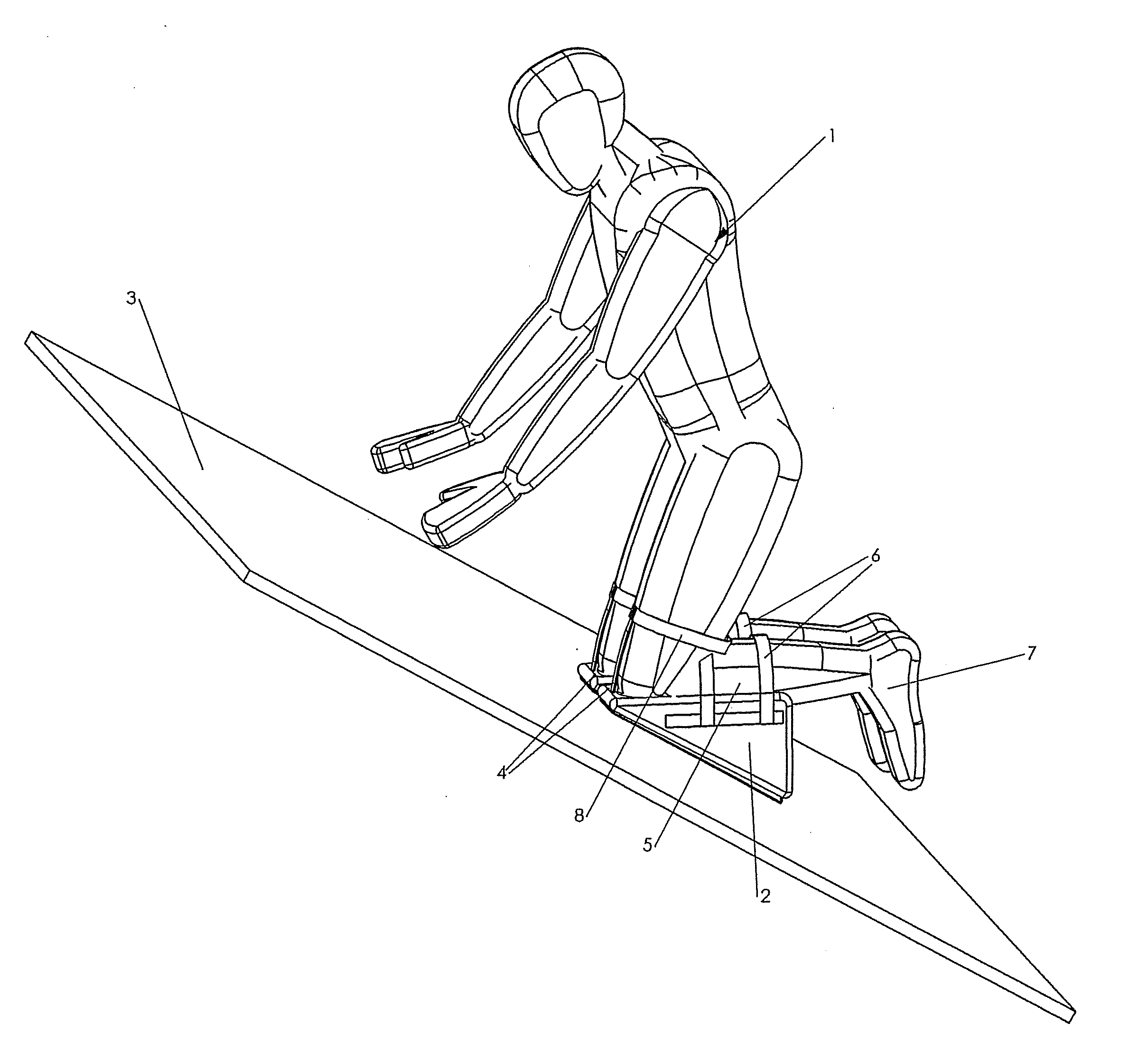
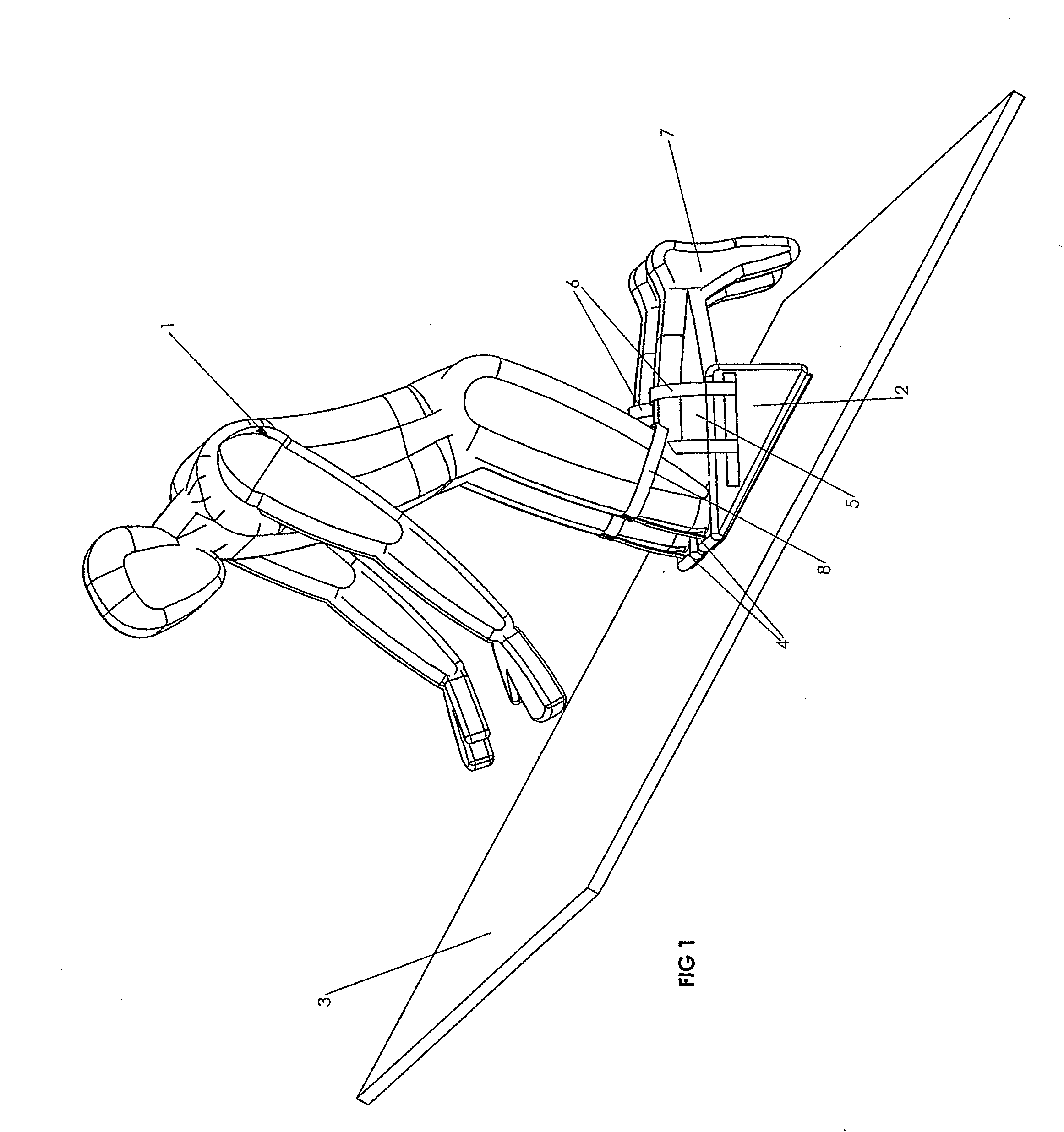
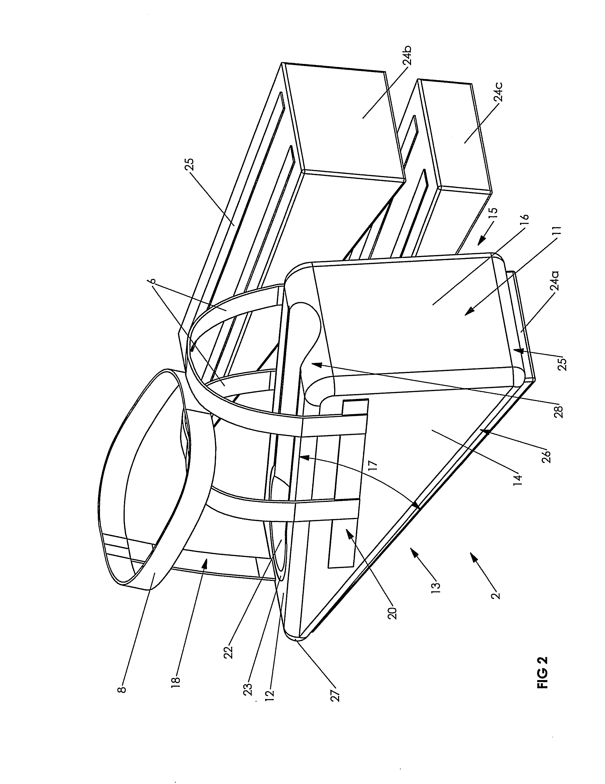
[0021]Referring to FIG. 1, roofer 1 is shown kneeling comfortably on inclined roof surface 3 using a pair of shin wedges 2 configured according to the present invention. The shape of the shin wedges is generally that of a wedge, having two non-parallel plane surfaces meeting at the thin side of the solid figure but not necessarily forming a sharp edge there. This shape could be described as a blunt wedge, but here is simply called “wedge”. The top surface may be not a flat plane, but rather (as will be described below) it may have a lengthwise depression to conform to the shin of the user. Opposite the thin blunt side is a thicker side to complete the solid triangle. The shin wedges are always worn so that the thin end is near the users knee (the proximal end) and the thick end is towards the foot (the distal end).

[0022]The shin wedge also usefully provides leverage, allowing the user to lever a knee up by rotation of the shin wedge about its distal edge.

[0023]In FIG. 1, for illustr...


PUM


Abstract

The invention is a wedge-shaped support adapted to be fastened to a user's lower leg to provide comfort when the user is kneeling on an inclined roof, used in pairs. Each shin wedge comprises a wedge of lightweight material capable of supporting the user's weight. The acute dihedral angle of each wedge is approximately equal to the pitch angle of the roof on which the wedge kneepads are being used, thereby providing a substantially horizontal upper kneeling surface when the wedge is oriented towards the peak of the roof. The wedge's lower surface typically comprises a durable pad that prevents premature abrasion of the lightweight material and improves grip onto the inclined surface. Each wedge's upper surface typically includes a soft layer that serves as an ergonomic kneeling pad for the user. An attachment harness secures the wedge kneepad to the user's shin and thigh or knee.

Description

FIELD OF THE INVENTION[0001]The invention relates to kneepads and shin pads and means for alleviating pressure and discomfort of the knees and legs of workers when they are working on inclined surfaces such as roofs.BACKGROUND TO THE INVENTION[0002]Kneeling to work on either a sloped surface such as a roof, or a horizontal surface such as a floor, presents an ergonomically challenging task that stresses a worker's legs and feet. When a worker is kneeling on any surface, either with both knees or partially kneeling on one knee, the front of the worker's knee makes contact and supports the bulk of the worker's weight. Contact with the surface is made, through the skin of course, by the upper part of the shin bone, also called the tibia, and sometimes but not necessarily the kneecap, also called the patella. This contact surface has no established name, and will here be called the “kneefront”. However the worker's toes must typically apply balancing pressure that varies with upper body...

Claims


Application Information

Patent Timeline
IPC IPC(8): A41D13/06
CPCE04D15/00A41D13/065
Inventor KIELLAND, PETER JOHANN
Owner VISIONARY TECH
Learn More