Armored Cable Cutter

Active Publication Date: 2009-06-18
IDEAL IND INC
View PDF18 Cites 5 Cited by
  • Summary
  • Abstract
  • Description
  • Claims
  • Application Information

AI Technical Summary

Benefits of technology

[0007]There is a blade handle pivotally connected to the cutter body. A cutting blade is mounted on the blade handle. A crank handle is rotatably mounted on the blade handle and the cutting blade is connected to the crank handle for rotation therewith. Pivoting of the blade handle causes the cutting blade to translate into and out of the channel, through the slot. The direction of translation into the channel defines a blade insertion direction. The distance in the blade insertion directio

Problems solved by technology

Therefore, there is empty space between

Method used


Image

  • Armored Cable Cutter
  • Armored Cable Cutter
  • Armored Cable Cutter

Examples


Example

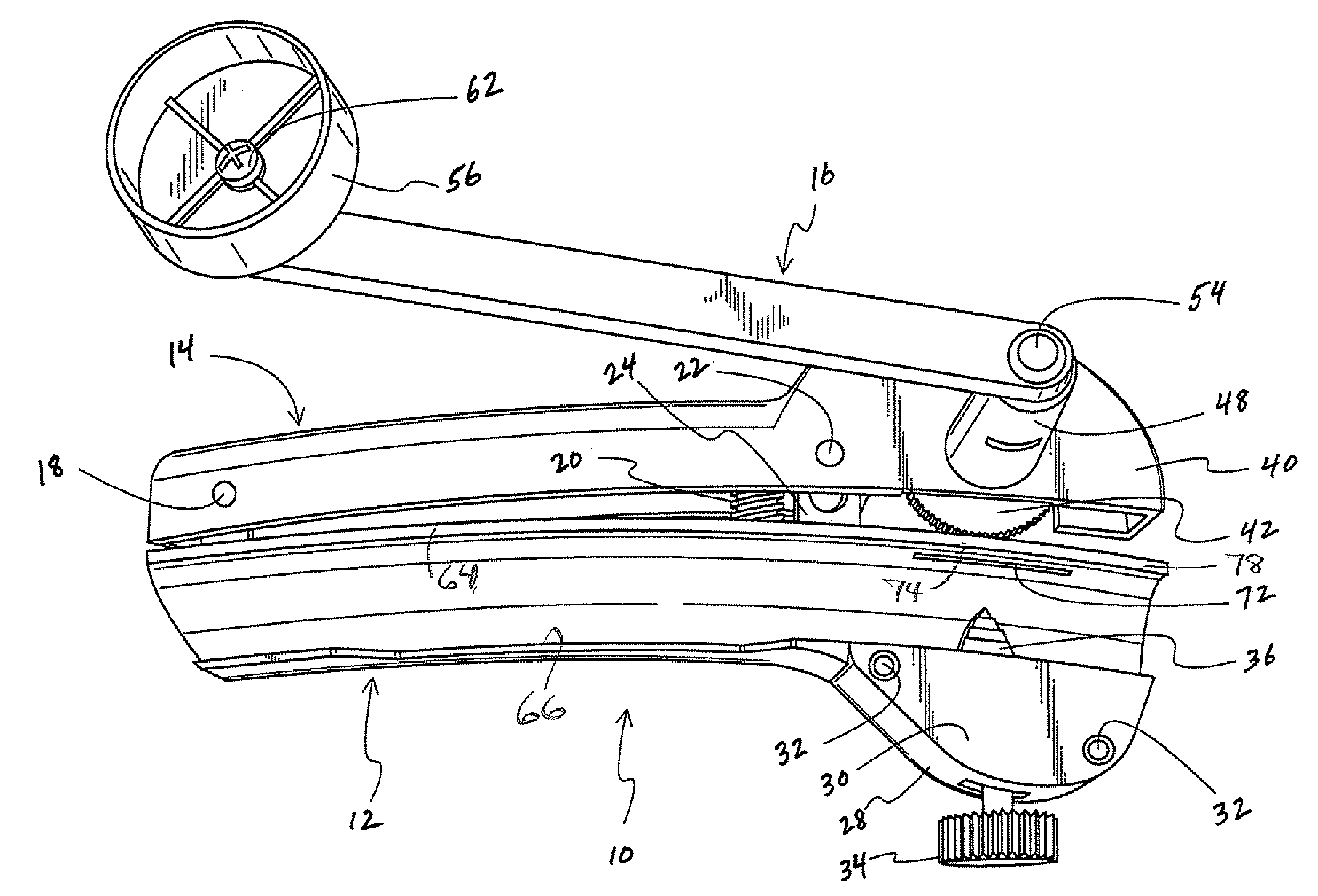
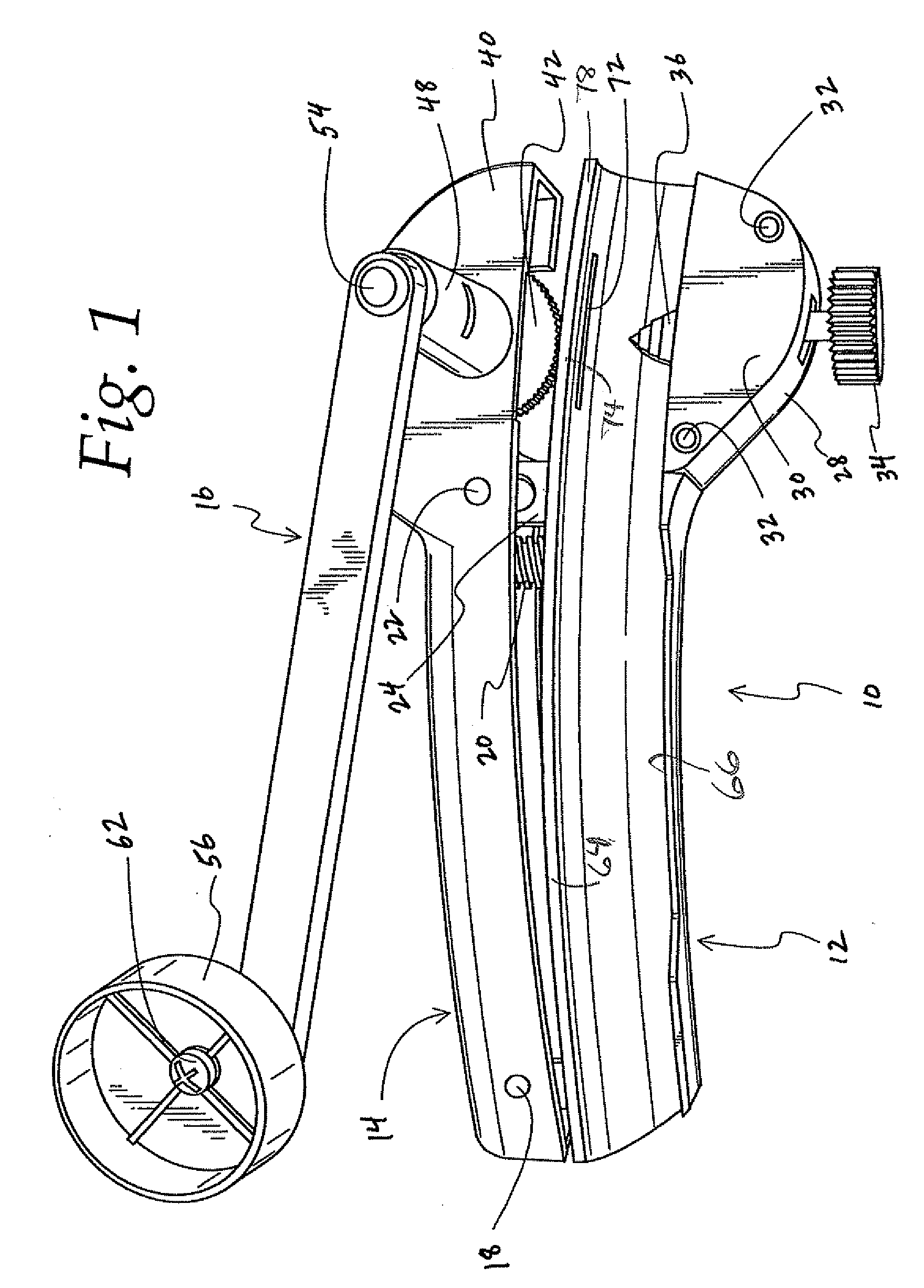
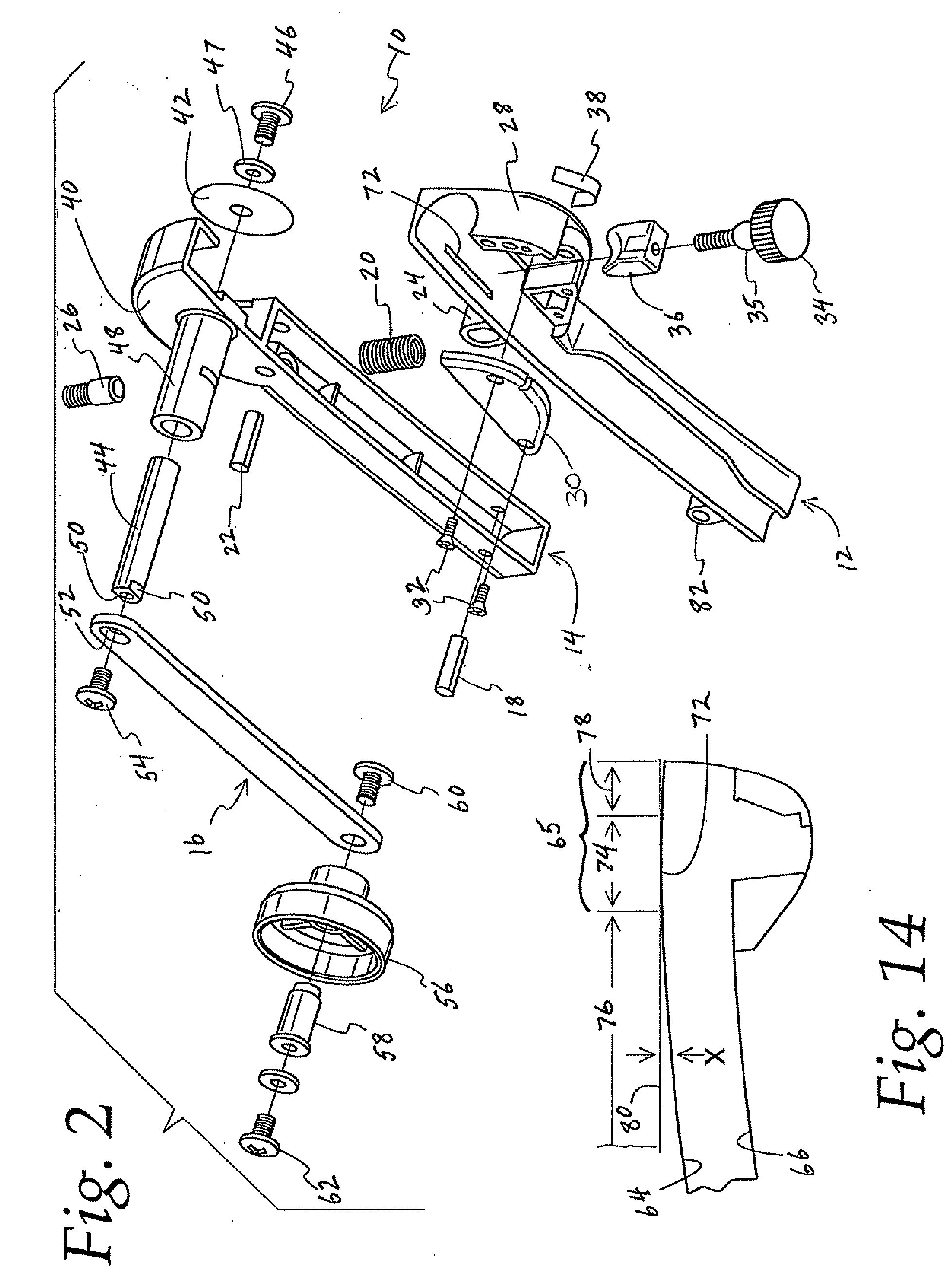
[0025]FIGS. 1 and 2 generally illustrate a preferred embodiment of the armored cable cutter 10 of the present invention. The cable cutter includes three primary components, a cutter body 12, a blade handle 14 and a crank handle 16. The left hand ends of the cutter body and blade handle, as viewed in FIG. 1, are pivotally connected to one another by a pivot pin 18. The pivot pin allows a user to grasp the cutter body and blade handle in one hand and either close these parts together by a squeezing action or open them by releasing the body and handle. A coil spring 20 is disposed between the cutter body 12 and blade handle 14 to bias them apart, i.e., to an open position. A spring pin 22 extends through the blade handle and engages a shackle 24 formed on the cutter body to limit the extent to which the coil spring 20 can separate the cutter body and blade handle. An adjuster 26 (FIG. 2) is threaded into an opening in the blade handle 14. The adjuster extends into the blade handle wher...


PUM

PropertyMeasurementUnit
Distanceaaaaaaaaaa

Abstract

A cutting tool for cutting the armor includes a cutter body having first and bottom entry walls defining a channel for receiving an armored cable. There is a slot in the first wall that affords reciprocating entry into the channel of a movable cutting blade from the outside of the wall. The direction of translation into the channel defines a blade insertion direction. The slot defines a slot segment of the first wall which in turn defines a base line. A stopper is mounted on the cutter body opposite the slot on the inside of the first wall. The stopper moves toward and away from the first wall to engage an armored cable placed in the channel and releasably press the armored cable against the slot segment of the first wall. The distance in the blade insertion direction of the bottom entry wall from the base line increases as the longitudinal distance from the slot segment increases to impart a curved configuration to the channel.

Description

BACKGROUND OF THE INVENTION[0001]The present invention relates to a hand tool for cutting armored cables such as BX, AC, or MC cables. In particular, the invention relates to an improvement in positioning the cable to have its metal casing cut longitudinally by a blade without damage to internal wires or conductors.[0002]Armored cable has a flexible aluminum or steel casing or jacket which protects a plurality of wires or conductors. The steel casing enables the cable to be resistant to damage. Typically, a tubular casing or outer jacket is created by helically winding a strip of aluminum or steel in an interlocking fashion. This method of construction creates grooves in the cable's casing that permit the cable to flex.[0003]Prior art armored cable cutters are shown, for example, in U.S. Pat. No. 3,851,387. The device of the '387 patent has been successful in replacing old cutting methods that rely on general purpose tools such as hacksaws or pliers for crimp cutting or twisting and...

Claims


Application Information

Patent Timeline
IPC IPC(8): H02G1/12B21F13/00
CPCH02G1/1297H02G1/1217
Inventor HARTRANFT, BRUCE W.
Owner IDEAL IND INC
Why Eureka
Try Eureka