
Device for Transmitting Rotary Motion

a technology of rotary motion and transmission device, which is applied in the direction of belt/chain/gearing, contact mechanism, belt/chain/gearing, etc., can solve the problems of not always the case, the drive source included does not immediately achieve the required powerful torque, and the imperfections of the drive sour

Inactive Publication Date: 2009-06-18
ABB POWER GRIDS SWITZERLAND AG
View PDF7 Cites 9 Cited by
  • Summary
  • Abstract
  • Description
  • Claims
  • Application Information

AI Technical Summary

Problems solved by technology

In certain cases, this can be quite unproblematic if the available drive source has a corresponding motion characteristic.
However, this is not always the case.
There are also situations where the drive source included does not immediately achieve a required powerful torque for the necessary short period.
It may also occur that both of these imperfections occur simultaneously as far as the available drive source is concerned.
), the viscosity of the oil is relatively high, and the returned rotary pulse may become too weak to ensure that the ratchet gearing will enter into a locking position.

Method used


Image

  • Device for Transmitting Rotary Motion
  • Device for Transmitting Rotary Motion
  • Device for Transmitting Rotary Motion

Examples


Embodiment Construction

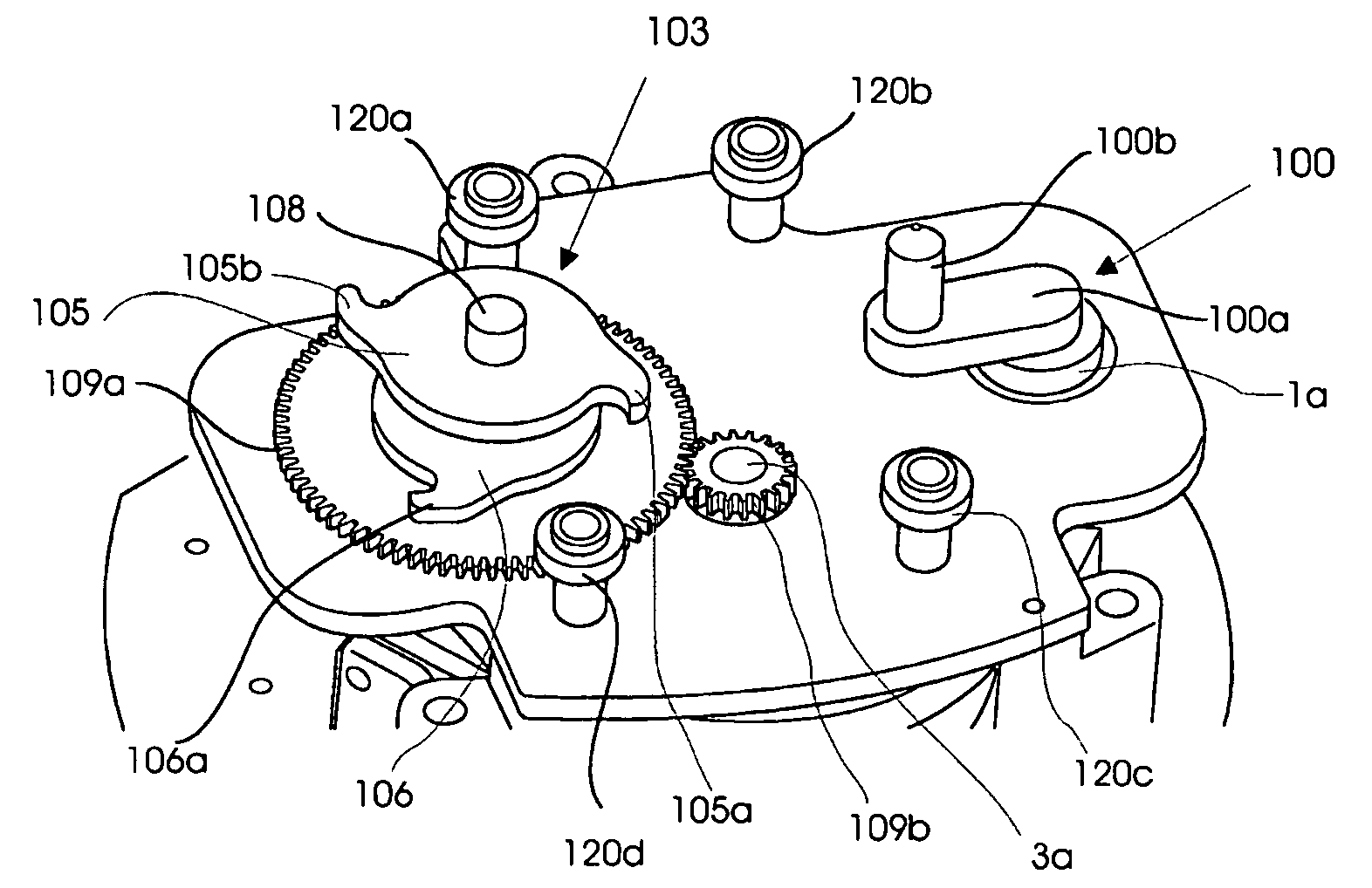
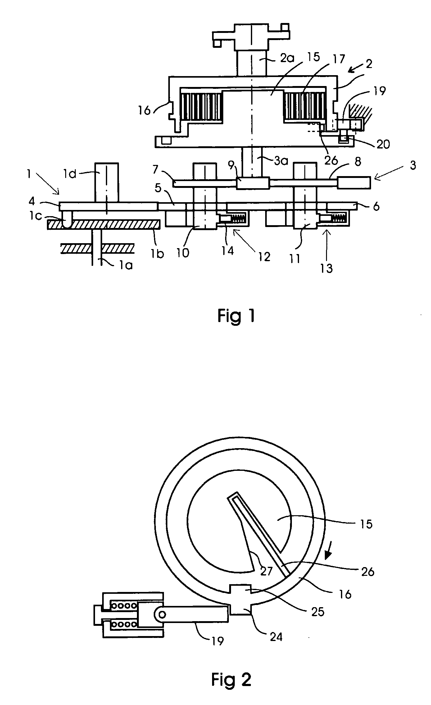
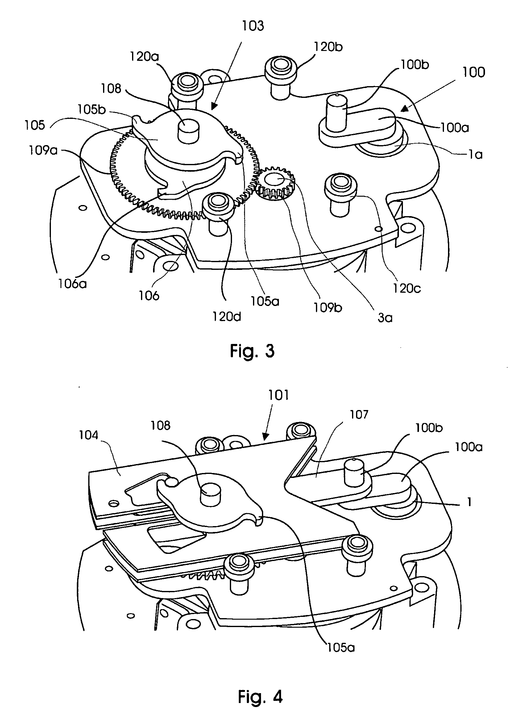
[0032]FIG. 3 shows a view of part of the drive system according to an embodiment of the invention, wherein the drive shaft 1a of a diverter switch rotates in different directions in dependence on whether it is a question of increasing or reducing the tension of the transformer. The output intermediate shaft 3a is connected to an intermediate body 3 (FIG. 1), not shown, and the associated energy accumulation member as well as a driven body 2 with a driven shaft 2a (FIG. 1).

[0033]For transformation of the alternating rotary motion of the drive shaft 1a into a unidirected rotary motion of the driven shaft 2a, an intermediate motion member 101 (FIGS. 3 and 4) is connected to the drive shaft 1a via a crank mechanism 100. The alternating rotary motion of the drive shaft 1a is thus transformed into an alternating linear motion of the motion member 101. This member, in its turn, is provided with intervention means 102 for transforming the linear motion into a unidirected rotary motion of th...


PUM


Abstract

Device for transmitting rotary motion in a diverter switch comprising a motion-transmitting member for transforming an alternating rotary motion of a drive shaft into a unidirected rotary motion of a driven body driven about driven shaft. The motion-transmitting member includes an intermediate body rotatable about an intermediate shaft. A mechanical energy accumulation member is connected to the driven body. The motion-transmitting member for transforming the alternating rotary motion of the drive shaft into a unidirected rotary motion of the driven shaft includes an intermediate motion member connected to a crank mechanism. The motion member includes an engagement mechanism for transforming the linear motion into a unidirected rotary motion of the intermediate shaft via drive members.

Description

FIELD OF THE INVENTION[0001]The present invention relates to a device for transmitting rotary motion, said device comprising a motion-transmitting member for transforming a driving body rotatable about an axis of rotation into rotary motion of a body driven about an axis of rotation.[0002]The invention further relates to a use of the invented device, in which the driven body is adapted to operate contacts of a diverter switch.BACKGROUND ART[0003]In certain contexts, there is a need to achieve a short, powerful rotary motion in a definite direction. In certain cases, this can be quite unproblematic if the available drive source has a corresponding motion characteristic. However, this is not always the case. It may occur that the available drive source is of such a kind that it carries out rotary motion in one direction as well as in the other direction.[0004]There are also situations where the drive source included does not immediately achieve a required powerful torque for the neces...

Claims


Application Information

Patent Timeline
Patent Type & Authority Applications(United States)
IPC IPC(8): F16H21/14F16H21/12
CPCH01H3/3052H01H3/34H01H3/46H01H3/48Y10T74/1503Y10T74/1508Y10T74/184Y10T74/1526Y10T74/1836H01H9/0027H01H9/00
Inventor JONSSON, LARS
Owner ABB POWER GRIDS SWITZERLAND AG
Learn More