Multi-channel perforated ticket separation mechanism

a perforated, multi-channel technology, applied in the direction of pre-printed tickets, instruments, de-stacking articles, etc., can solve the problems of ticket dispenser failure, substantial loss of revenue, and inconvenience for users, and achieve efficient power transfer, compact geometry, and efficient transfer

Active Publication Date: 2009-06-18
INTRALOT
View PDF24 Cites 17 Cited by
  • Summary
  • Abstract
  • Description
  • Claims
  • Application Information

AI Technical Summary

Benefits of technology

[0010]The feed mechanism according to another embodiment of this invention includes a compact transmission wherein drive is efficiently transferred from a vertically-oriented feed motor to horizontally-oriented feed rollers, providing efficient power transfer, a compact geometry, and flexible placement of drive train components.

Problems solved by technology

A total failure of a ticket dispenser preventing it from dispensing tickets results in a substantial loss of revenue; and in addition, such a failure incurs a substantial cost in having to service the ticket dispenser in the field.
However, partial failures of a ticket dispenser can also be costly.
For example, if the vending machine has multiple channels to dispense a variety of tickets, failure of a ticket separation mechanism that services all of the channels requires servicing and / or replacement of the entire mechanism.
Needless to say, such a situation is very problematic to the issuer of the lottery ticket as well as the customer.
Another potential cause of improper ticket dispenser operation is the transmission driven mechanism feeding the supply of tickets to the separation mechanism for discharge to the customer.
The arrangement of the ticket feed mechanism in many known systems is generally not optimized for compactness because of mechanical difficulties and expense involved in the axis of drive rotation.
Another problem with known ticket dispensers is the difficulty in unloading the last ticket in a strip of tickets.
In such a situation, the removal of the last ticket can become time-consuming and mechanically involved.

Method used


Image

  • Multi-channel perforated ticket separation mechanism
  • Multi-channel perforated ticket separation mechanism
  • Multi-channel perforated ticket separation mechanism

Examples


Embodiment Construction

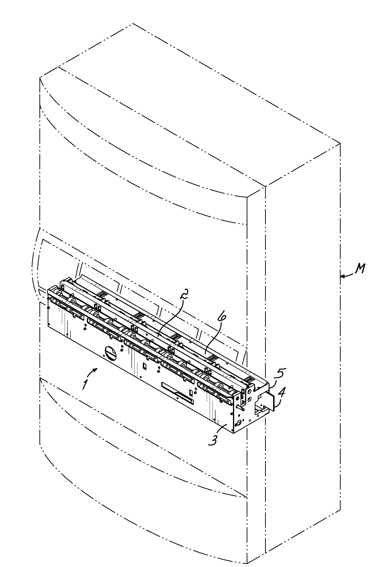
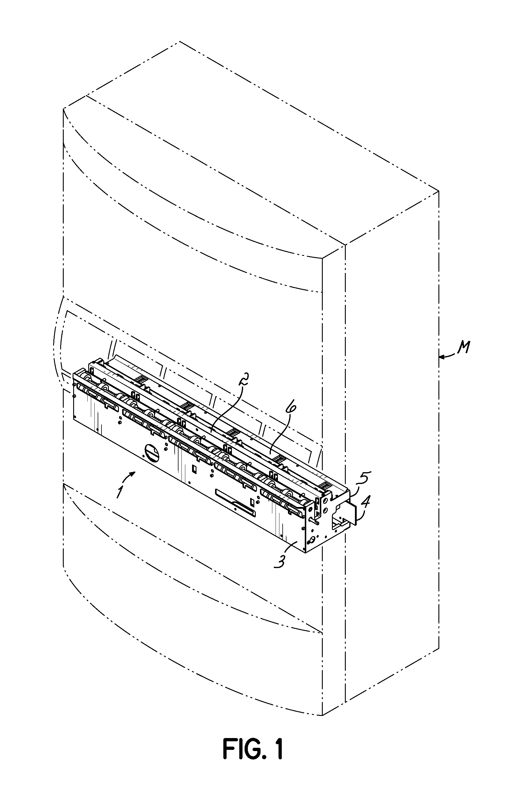
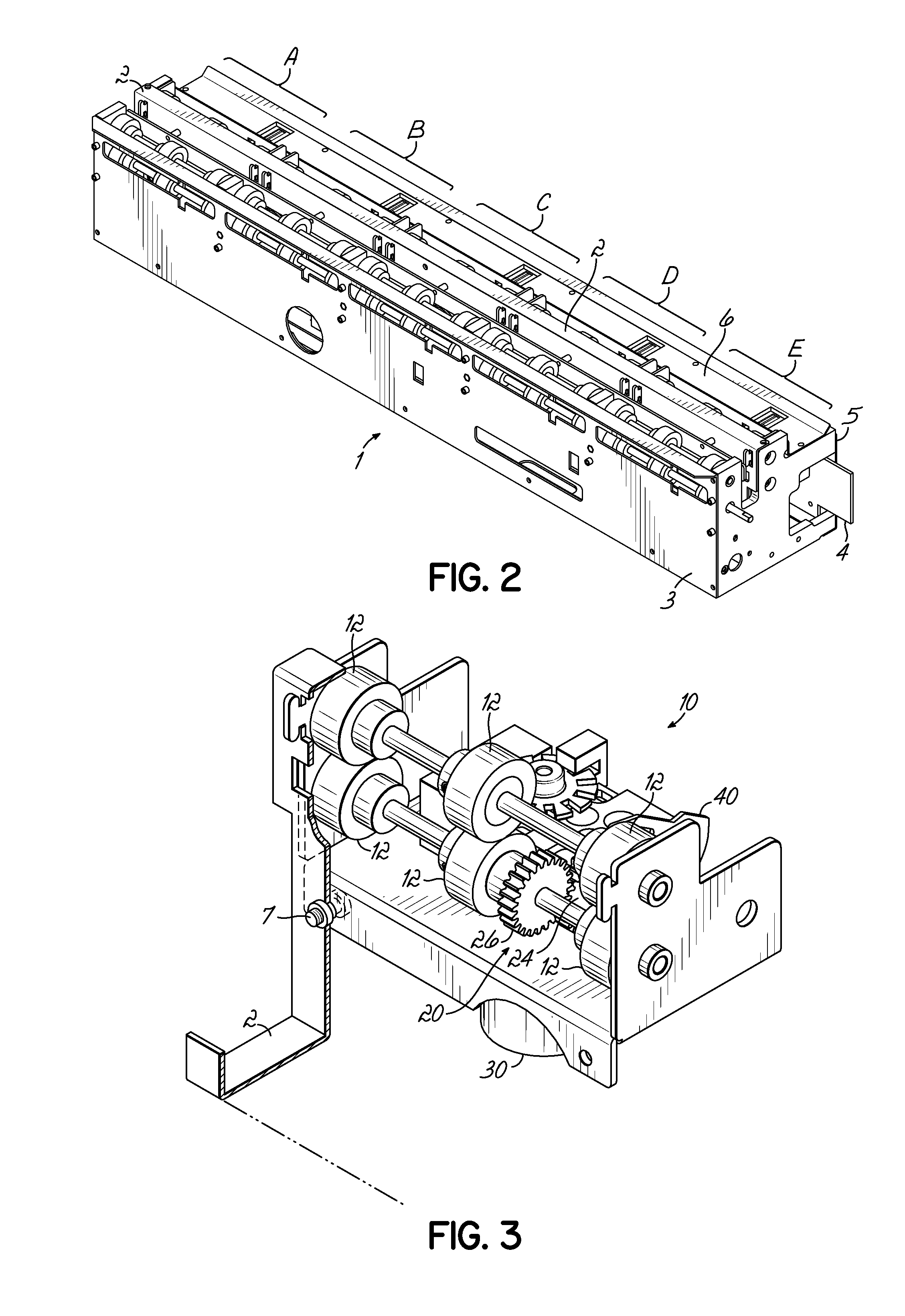
[0026]A ticket separation mechanism for lottery ticket dispensers operates by the use of two sets of feed rollers: bin rollers and exit rollers. Each of the sets of rollers may have a separate motor associated with it. Strips of lottery or other types of serially connected tickets feed into the bin rollers and past a separation zone. A separation mechanism separates the ticket strip at a perforation joining adjacent tickets such that the tickets in front of the separation zone can be dispensed while the strip behind the separation zone remains within the machine. The separation mechanism may be a burster such as that disclosed in U.S. Pat. No. 4,982,337, a cutter or other device known in the art. The exit rollers, on the other side of the separation zone, feed the tickets out to the ticket dispensing area to be received by the customer. In a multi-channel assembly, each of the multiple channels may include its own set of bin rollers and exit rollers to feed the ticket strip associat...


PUM


Abstract

A multi-channel separation mechanism assembly for a lottery or other ticket dispensing machine includes a separate detachable feed mechanism associated with each separate feed channel, such that the feed mechanism for a single channel can be removed and replaced without replacing the entire assembly. Each such detachable feed mechanism includes a compact transmission wherein drive is efficiently transferred from a vertically-oriented feed motor to horizontally-oriented feed rollers. Each feed channel is additionally equipped with a bidirectional mechanical flag which triggers an optical sensor to detect presence of a ticket strip in the channel while still allowing appropriate reverse motion of the ticket strip within the associated channel.

Description

CROSS-REFERENCE TO RELATED APPLICATIONS[0001]This application claims priority to U.S. Provisional Application No. 61 / 013,686, filed Dec. 14, 2007, which is hereby incorporated by reference.FIELD OF THE INVENTION[0002]This invention relates to item dispensers and more particularly, to an apparatus and method for dispensing tickets from strips of tickets.BACKGROUND OF THE INVENTION[0003]Various types of machines have been developed for dispensing and vending lottery tickets that are printed in long strips, wherein each ticket is separable from another ticket by a perforation line. The tickets are generally stored in a fan-fold form in a vending machine and are dispensed upon the customer paying for the tickets. The tickets are printed on a relatively heavy stock and hence, have some stiffness but are flexible. The tickets can vary substantially in size and thickness depending on the lottery game, the design by the issuer of the ticket, etc. Examples of such machines are disclosed in U...

Claims


Application Information

Patent Timeline
Patent Type & Authority Applications(United States)
IPC IPC(8): G07F11/16B65H35/10
CPCG07B3/02G07F11/16G07B5/02G07F17/42Y10T225/16Y10T225/371Y10T225/35
Inventor MIRKOVIC, ZORANPERIN, JR., JOSEPH C.
Owner INTRALOT
Why Eureka
Try Eureka