[0006]An object of the present invention is to extend the range of suitability of the ring and blocking-hoop fastener system to applications in which it is necessary to remove the dispenser unit from the reservoir. Another object of the present invention is to make disassembly possible, without adding additional pieces to the dispenser. Manufacture, implementation, and
assembly that are simple and low cost are also objects of the present invention.
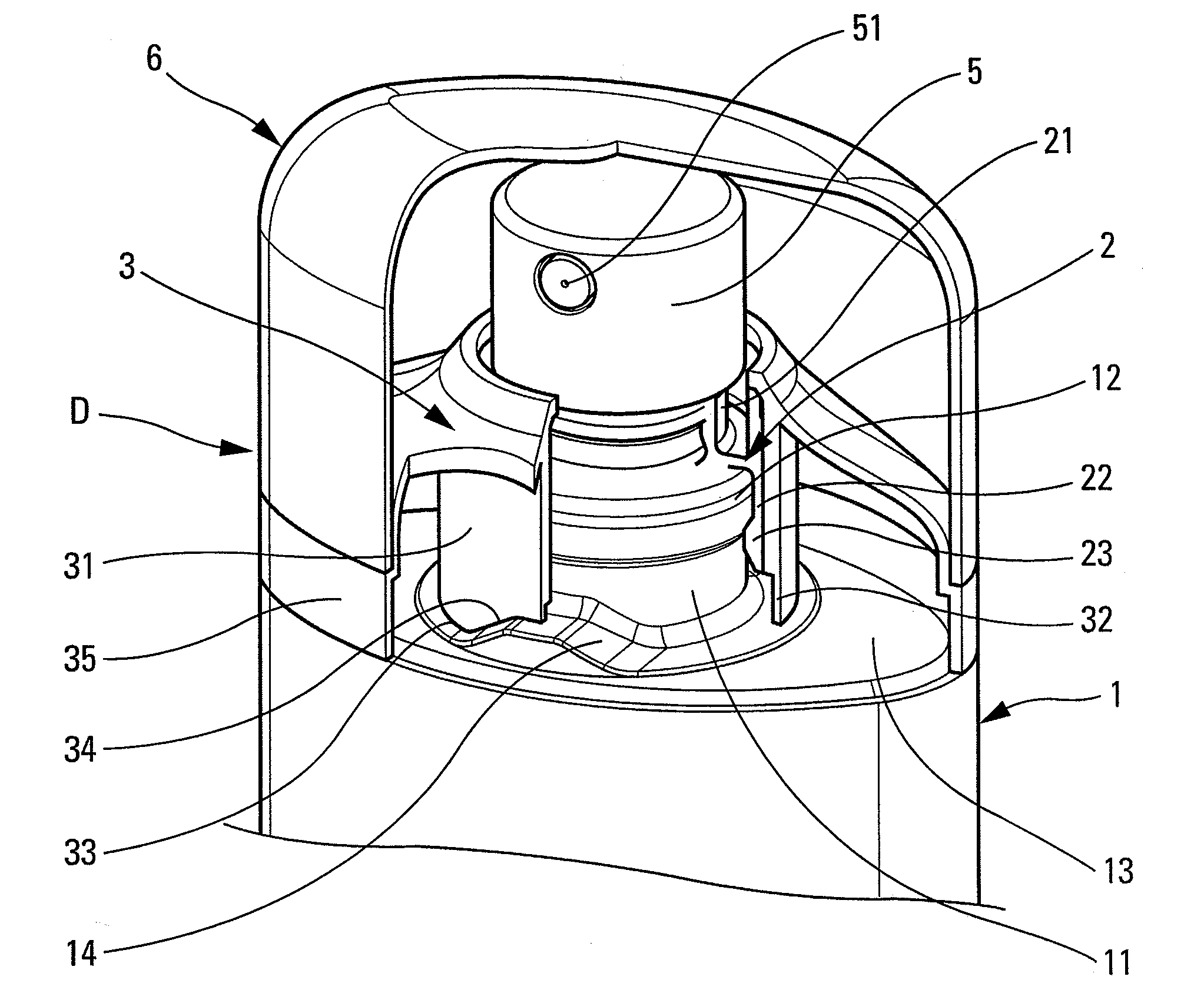
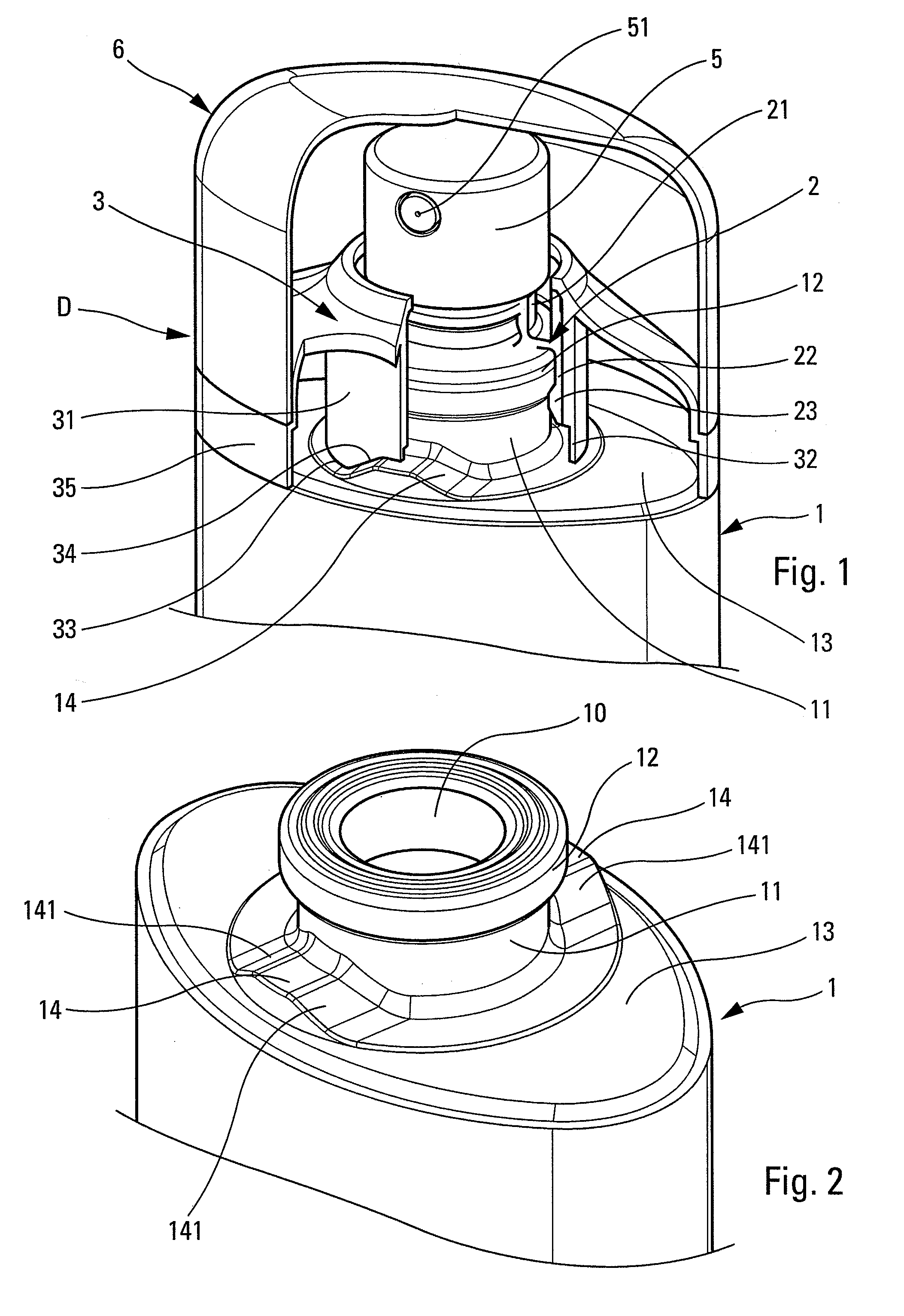
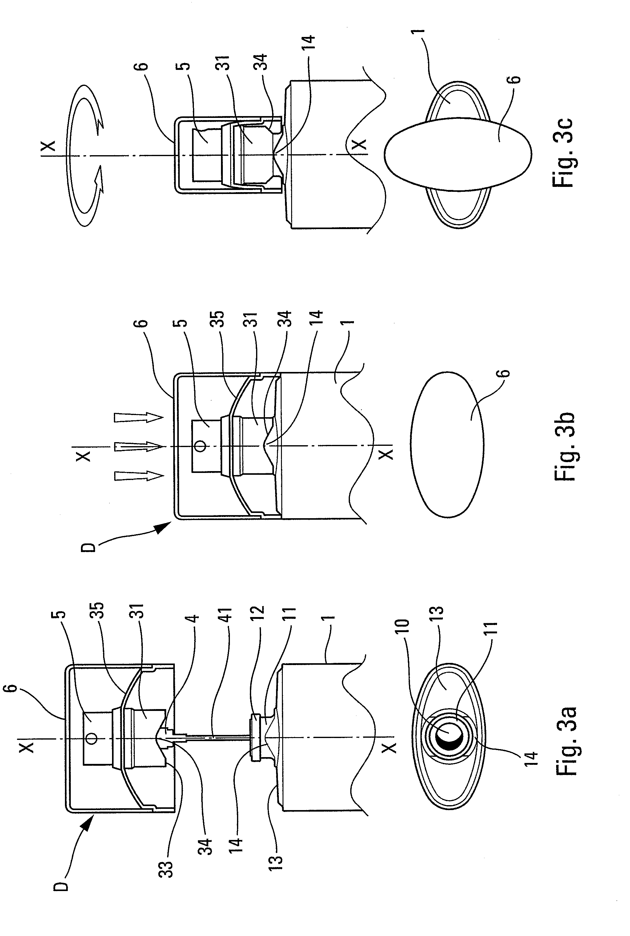
[0007]To achieve these objects, the present invention proposes A fluid dispenser comprising a fluid reservoir having a neck defining an opening and an axis X, the neck projecting axially from a shoulder, a dispenser unit comprising a dispenser member, such as a pump or a valve, and a fastener system for fastening the dispenser member on the neck of the reservoir, the fastener system comprising a fastener ring that is engaged with the neck and a blocking hoop that is engaged axially around the ring for blocking the ring on the neck in the final assembled position, disassembly means for axially moving the hoop relative to the ring, from the final assembled position to a disassembled position in which the hoop does not block the ring on the neck, such that the unit can be removed from the neck, the disassembly means comprising two elements capable of turning mutually relative to each other about the axis X, the dispenser being characterized in that one element of the disassembly means is secured to the reservoir, while an other element is secured to the dispenser unit. The present invention thus avoids partial or total destruction of the hoop, the ring, or the neck of the reservoir.
[0008]In an advantageous aspect of the invention, the other element is integral with the hoop. Thus, turning the hoop relative to the reservoir is transformed into axial movement of the hoop relative to the reservoir. It is advantageous to act directly on the hoop which tightly surrounds the ring, thus avoiding any plastic or elastical deformation of the fastener system. Upon axial pushing from beneath on the hoop, its moving relative to the ring is achieved.
[0010]In another advantageous aspect of the invention, the hoop is surrounded by an outer skirt that masks both the hoop and the disassembly means in the final assembled position. The outer skirt may serve as an outer covering for the dispenser unit, imparting an attractive appearance thereto. However, it is possible to use the outer skirt to impart the turning movement required to move the blocking hoop relative to the ring.
[0011]According to another advantageous characteristic of the invention, intermediate clearance is provided between the hoop and the ring in the disassembled position and / or in the pre-assembled position, so as to enable the ring to move radially outwards while it is being disassembled from and / or assembled to the neck. This characteristic, which may be protected independently of the disassembly means of the invention, makes it possible to elongate or extend the hoop, thereby enabling the hoop to reach quickly the shoulder of the reservoir where the ramp is advantageously formed, without the blocking function being provided by the entire height of the hoop. Thus, it suffices to move the hoop axially over a very limited height in order to unblock the ring from the neck. This avoids moving the bottom end of the hoop relative to the ring to above the inner fastener profile(s). The extension of the hoop forming the intermediate clearance does not enable the ring to be blocked on the neck, but, in contrast, serves as an axial-thrust transmission element while the hoop is turning on the neck. The non-blocking extension of the hoop also enables the ring to be pre-assembled inside the hoop before the dispenser unit is assembled for the first time on the reservoir neck, and without the ring projecting out from the hoop. The fastener ring, which is a fragile element since it is deformable, is thus protected inside the hoop in which it is completely inscribed. It should be clearly understood that this last characteristic (the ring protected in the hoop) may be implemented independently of the disassembly means of the present invention.

