Reflective multi-turn encoder

a multi-turn encoder and encoder technology, applied in the direction of optical mechanical conversion of sensor output, instruments, etc., can solve the problems of limited precision of injection molded gears, limited conventional implementations of magnetic encoders

Inactive Publication Date: 2009-06-18
AVAGO TECH ECBU IP (SINGAPORE) PTE LTD
View PDF10 Cites 115 Cited by
  • Summary
  • Abstract
  • Description
  • Claims
  • Application Information

AI Technical Summary

Problems solved by technology

Conventional implementations of magnetic encoders are limited because of prevalent interference by external

Method used


Image

  • Reflective multi-turn encoder
  • Reflective multi-turn encoder
  • Reflective multi-turn encoder

Examples


Embodiment Construction

[0020]In the following description, specific details of various embodiments are provided. However, some embodiments may be practiced with less than all of these specific details. In other instances, certain methods, procedures, components, structures, and / or functions are described in no more detail than to enable the various embodiments of the invention, for the sake of brevity and clarity.

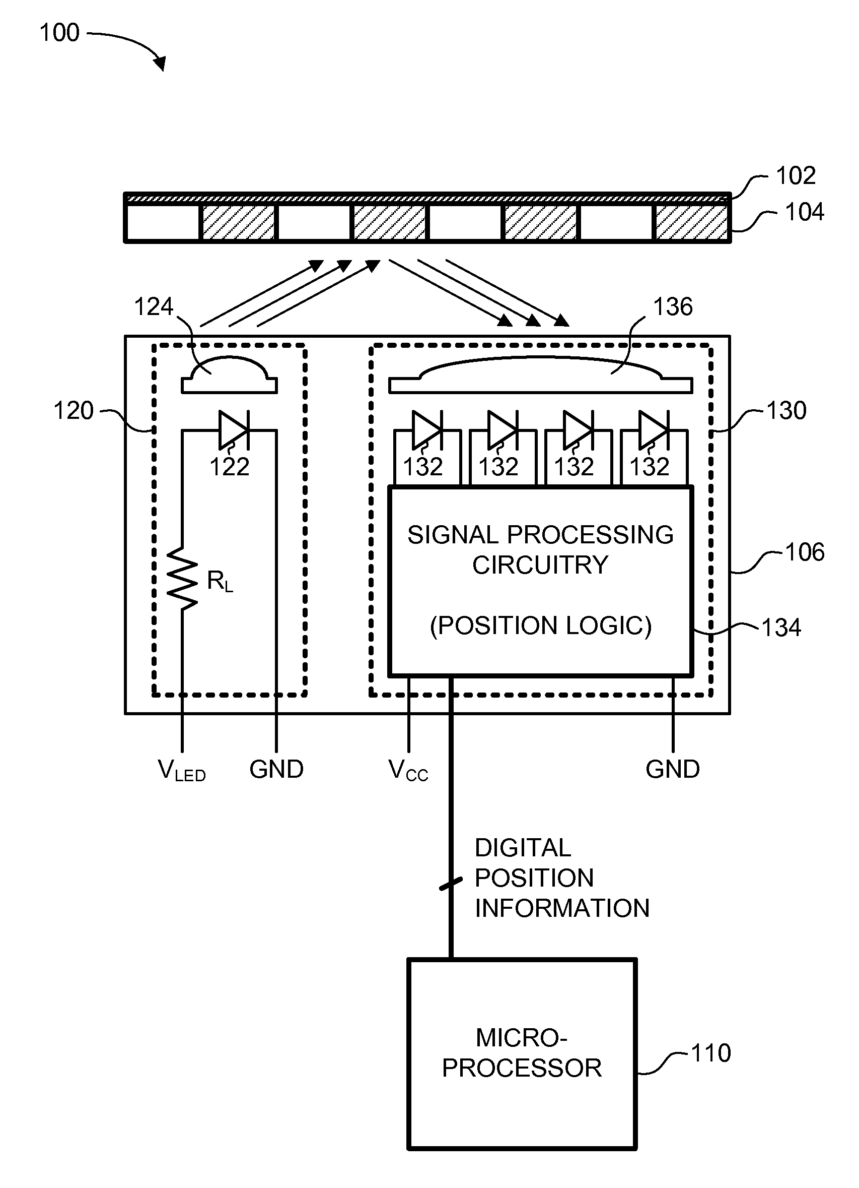
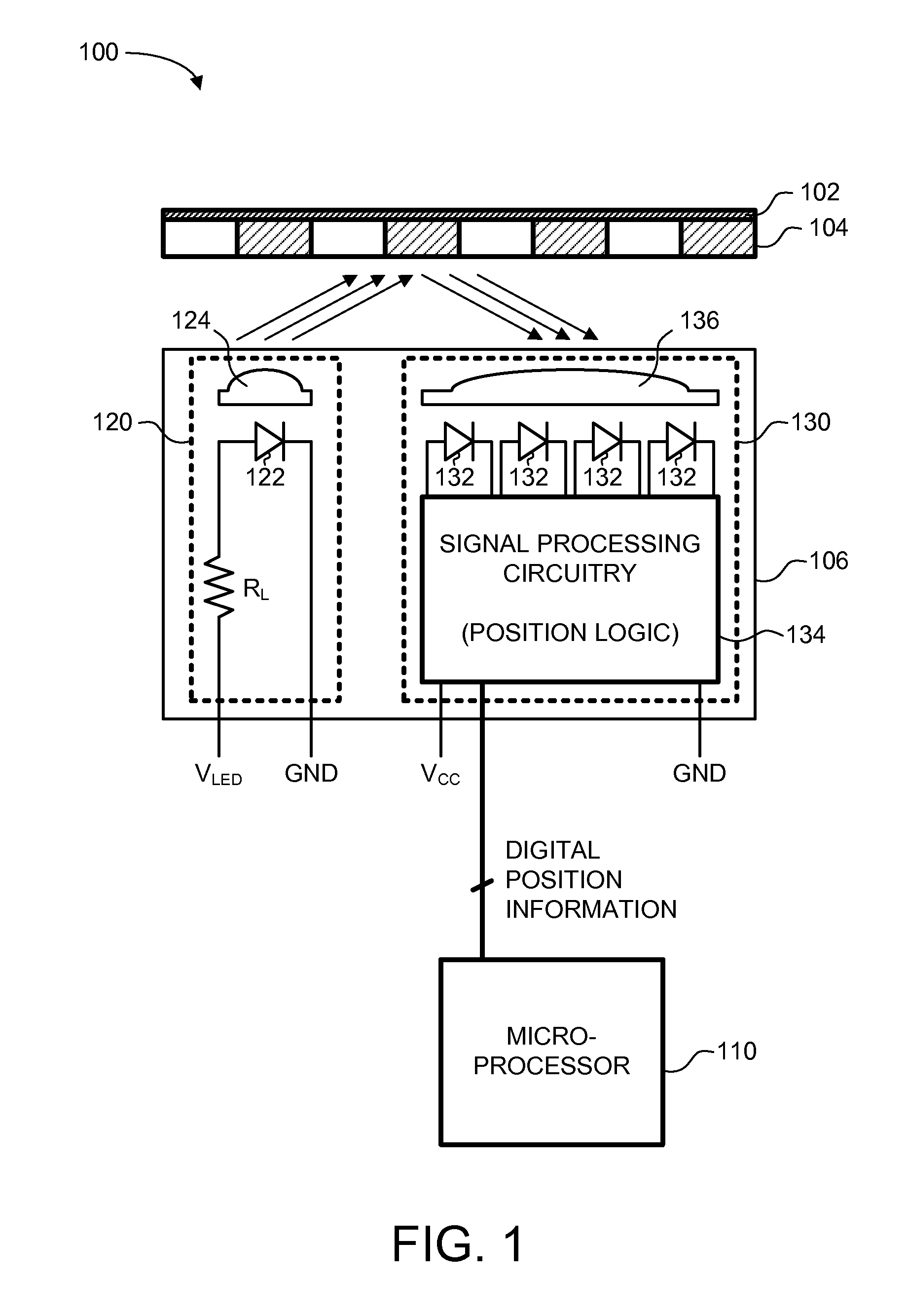
[0021]While many embodiments are described herein, at least some of the described embodiments relate to a multi-turn encoder which implements a reflective optical technology. In particular, a reflective sensor can be placed on a single side or both sides of a gear (or gear train) to monitor a rotational movement of the gear (or gear train). Using a reflective optical sensing technology, in contrast to a transmissive optical sensing technology, allows smaller form factors and more flexibility in gear placement. Other embodiments are also described below with specific reference to the corresponding...


PUM


Abstract

A reflective optical encoder for a gear train. The reflective optical encoder includes a gear train with a plurality of gears. Each of the gears is operably coupled to at least one other gear of the plurality of gears. A reflective code pattern is accessible on a surface of at least one of the gears. A reflective optical sensor detects light reflected by the reflective code pattern. Position logic coupled to the optical sensor determines a rotational parameter of the gear train based on the light reflected by the reflective code pattern. Additionally, the position logic may determine rotational parameter of a pinion coupled to the gear train based on the rotational parameter of the gear train.

Description

BACKGROUND OF THE INVENTION[0001]Optical encoders are used to monitor the motion of, for example, a gear or a shaft such as a crank shaft. Optical encoders can monitor the motion of a gear in terms of position and / or number of revolutions of the gear. Optical encoders are employed in systems to provide high resolution within tight size limitations.[0002]An optical encoder may be used to monitor rotational motion of a gear. For monitoring gear movement, conventional multi-turn optical encoders typically employ magnetic or transmissive encoding technology. Conventional implementations of magnetic encoders are limited because of prevalent interference by external magnetic fields.[0003]Transmissive optical encoders typically use a code wheel integrated into the body of a gear to modulate light as the gear rotates. In a transmissive code wheel, the light is modulated as it passes through transmissive sections of a track on the code wheel. The transmissive sections are separated by non-tr...

Claims


Application Information

Patent Timeline
IPC IPC(8): G01D5/34
CPCG01D5/04G01D5/34792G01D5/34715G01D5/347
Inventor LEE, SZE KUANGWONG, WENG FEI
Owner AVAGO TECH ECBU IP (SINGAPORE) PTE LTD
Why Eureka
Try Eureka