Perpendicular magnetic recording write head with slanted magnetic write pole

a write head and magnetic technology, applied in the direction of maintaining the head carrier alignment, recording information storage, instruments, etc., can solve the problem of reducing the likelihood of erasure on adjacent tracks, and achieve the effect of reducing the probability of erasure, reducing the write field gradient, and reducing the width of the magnetic cor

Inactive Publication Date: 2009-06-18
WESTERN DIGITAL TECH INC
View PDF22 Cites 40 Cited by
  • Summary
  • Abstract
  • Description
  • Claims
  • Application Information

AI Technical Summary

Benefits of technology

[0010]The write head with the slanted WP results in a larger write field. The peak field, which occurs approximately at the edge of the end of the slanted WP adjacent the gap layer between the WP and the TS, is increased, which enables the gap layer to be made thinner. A thinner gap layer results in a better write field gradient. The write head with slanted WP also results in a smaller magnetic core width (MCW), which is the written width on the medium, which reduces the likelihood of erasure on adjacent tracks, especially when writing at a large skew angle relative to a data track.
[0011]The write head with slanted WP may also include a pair of side shields located on opposite sides of the WP in the cross-track direction and separated from the WP by a nonmagnetic gap layer. The side shields control the write width and help reduce adjacent-track-erasure. The write head with slanted WP may also include a leading shield (LS) located on the opposite side of the WP from the TS in the along-the-track direction and separated from the WP by a nonmagnetic gap layer. The LS reduces the fringing field at the leading edge of the WP and helps control erasure width at the skew angle.

Problems solved by technology

The write head with slanted WP also results in a smaller magnetic core width (MCW), which is the written width on the medium, which reduces the likelihood of erasure on adjacent tracks, especially when writing at a large skew angle relative to a data track.

Method used


Image

  • Perpendicular magnetic recording write head with slanted magnetic write pole
  • Perpendicular magnetic recording write head with slanted magnetic write pole
  • Perpendicular magnetic recording write head with slanted magnetic write pole

Examples


Embodiment Construction

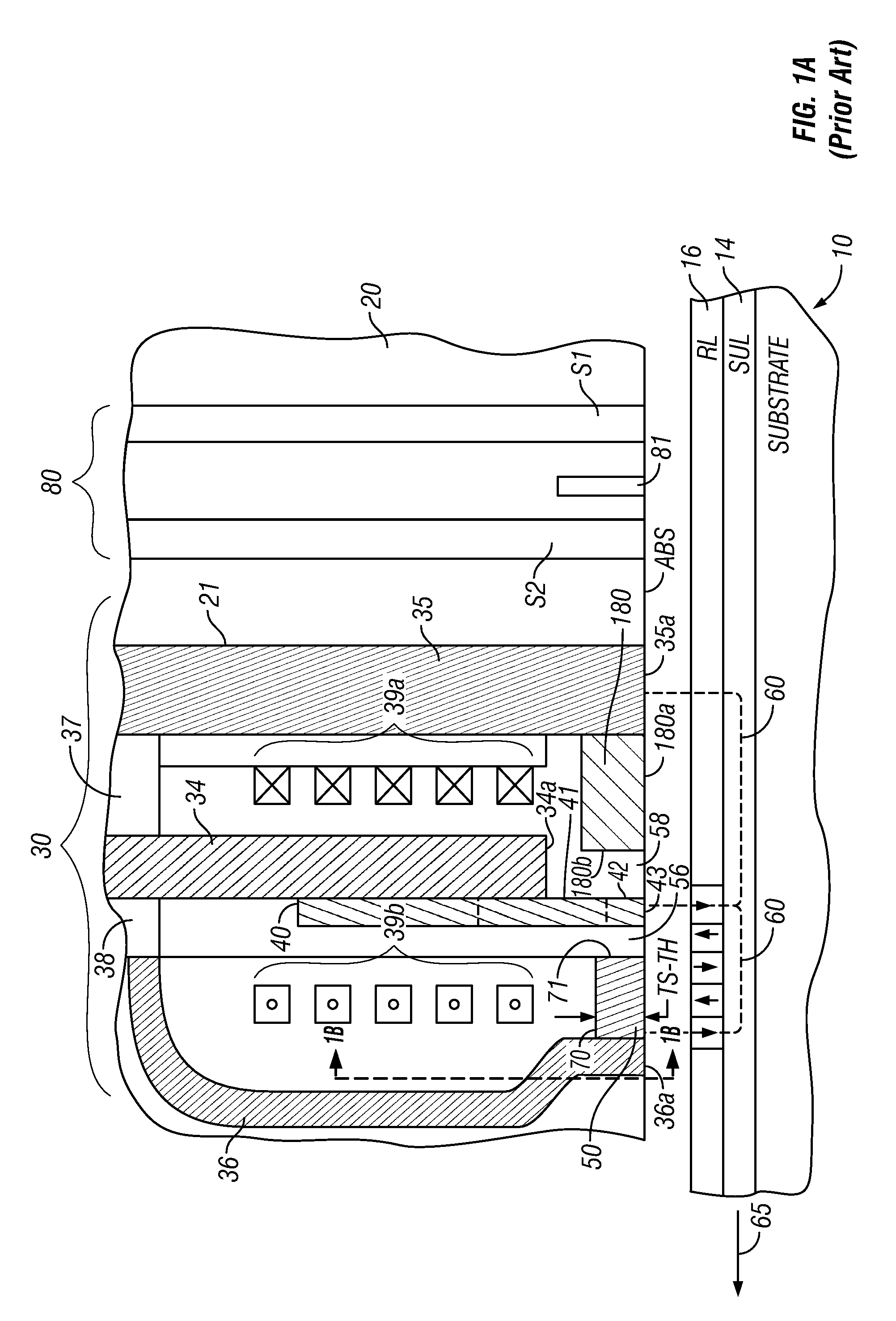
[0026]FIG. 1A is a side sectional view of a prior art perpendicular magnetic recording write head, read head and a recording medium taken through a central plane that intersects a data track on the medium. As shown in FIG. 1A, a “dual-layer” medium 10 includes a perpendicular magnetic data recording layer (RL) 16 on a “soft” or relatively low-coercivity magnetically permeable underlayer (SUL) 14 formed on the disk substrate 12. This type of medium is shown with a single write pole type of recording or write head 30. The recording head is typically formed on a trailing surface 21 of an air-bearing slider 20 that has its air-bearing surface (ABS) supported above the surface of medium 10. The recording head 30 includes a yoke made up of the main pole 34, first or leading flux return pole 35, second or trailing flux return pole 36 and yoke studs 37, 38 connecting the main pole and return poles 35, 36 respectively; and a thin film coil 39a, 39b shown in section around main pole 34. The m...


PUM

PropertyMeasurementUnit
angleaaaaaaaaaa
angleaaaaaaaaaa
angleaaaaaaaaaa

Abstract

A perpendicular magnetic recording write head is formed on the trailing surface of a head carrier or slider that has an air-bearing surface (ABS) oriented generally parallel to the surface of the disk during operation of the disk drive. The write head has a slanted ferromagnetic write pole (WP) that forms an angle between about 5 and 20 degrees from a normal to the ABS. The slanted WP is formed over the generally planar surface of the ferromagnetic main pole and the slanted surface of a support layer located between the ABS and the recessed end of the main pole. A trailing shield (TS) has a slanted face that is generally parallel to and spaced from the slanted WP, with a nonmagnetic gap layer located between the slanted face of the TS and the slanted WP.

Description

BACKGROUND OF THE INVENTION[0001]1. Field of the Invention[0002]This invention relates generally to perpendicular magnetic recording write heads for use in magnetic recording disk drives.[0003]2. Description of the Related Art[0004]Perpendicular magnetic recording, wherein the recorded bits are stored in a perpendicular or out-of-plane orientation in the recording layer, is a promising path toward ultra-high recording densities in magnetic recording hard disk drives. The recording or write head in perpendicular magnetic recording disk drives includes a write pole for directing a magnetic field to data tracks in the recording layer, and one or more return poles for return of magnetic flux from the recording layer.[0005]The write head may also include a trailing shield (TS) of magnetically permeable material that faces the recording layer and is spaced from the write pole in the along-the-track direction by a nonmagnetic gap. The TS slightly alters the angle of the write field and mak...

Claims


Application Information

Patent Timeline
Patent Type & Authority Applications(United States)
IPC IPC(8): G11B5/60
CPCG11B5/1278G11B5/3116G11B5/3163G11B5/315G11B5/3146
Inventor HSIAO, WEN-CHIEN DAVIDNIKITIN, VLADIMIR
Owner WESTERN DIGITAL TECH INC
Why Eureka
Try Eureka