Method and system for improving laser alignment and optical transmission efficiency of an energy assisted magnetic recording head

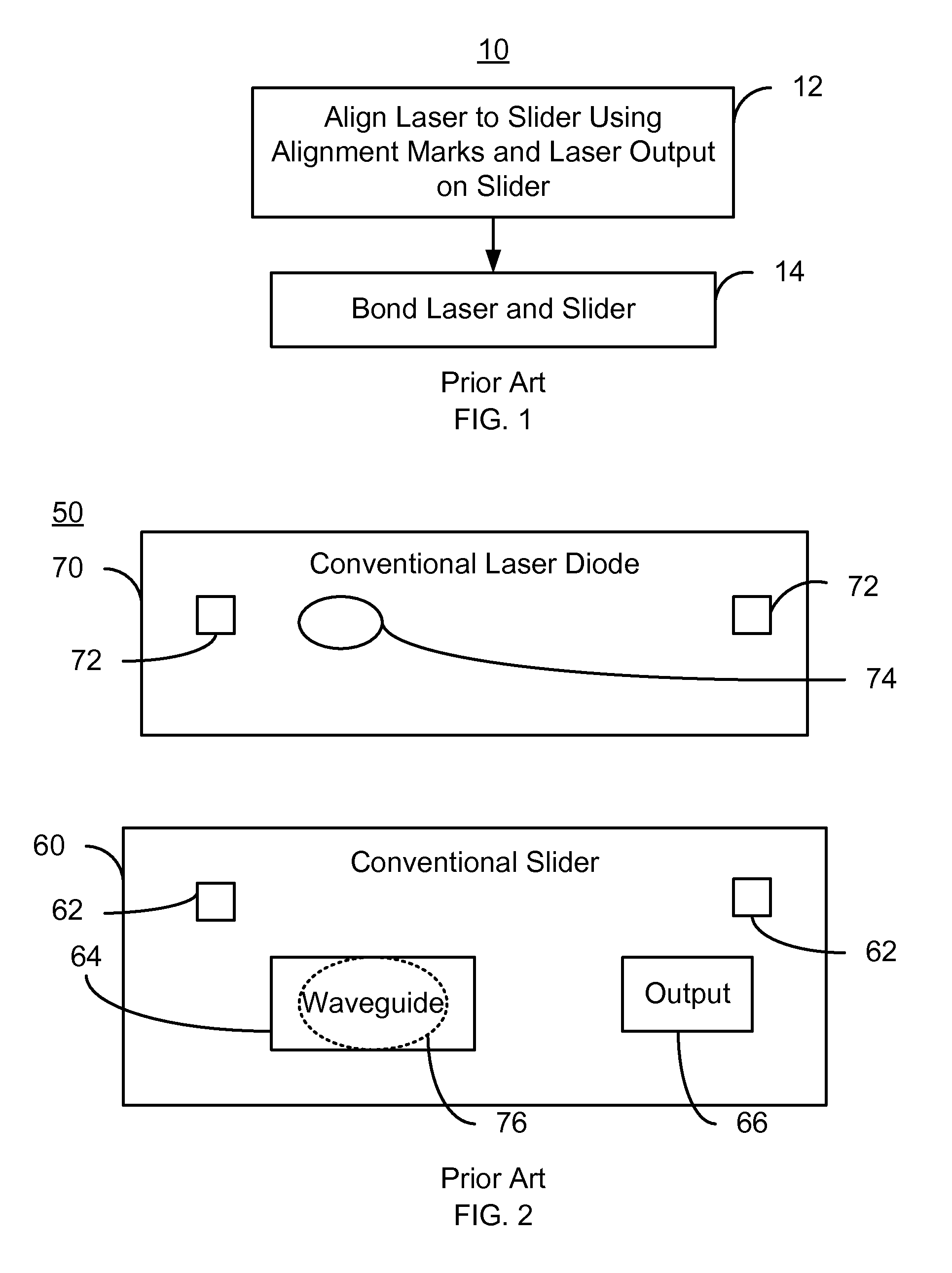
a laser alignment and optical transmission efficiency technology, applied in the field of laser alignment and optical transmission efficiency improvement of energy assisted magnetic recording head, can solve the problems of difficult alignment between the laser spot b>76/b> and the waveguide b>64/b>, time-consuming and laborious, and achieve the effect of reducing back reflection of energy

Active Publication Date: 2014-03-25
WESTERN DIGITAL TECH INC
View PDF9 Cites 158 Cited by
  • Summary
  • Abstract
  • Description
  • Claims
  • Application Information

AI Technical Summary

Benefits of technology

[0007]An EAMR disk drive includes a media, a laser, and a slider coupled with the laser. The laser for provides energy. The slider has an air-bearing surface, a laser input side, an EAMR transducer and an antireflective coating (ARC) layer occupying a portion of the laser input side. The ARC layer is configured to reduce back reflections of the energy. The EAMR transducer includes a write pole, a waveguide optically coupled with the laser and at least one coil. The waveguide has a waveguide input. A portion of the ARC layer resides between the laser and the waveguide input. A method aligns the laser to the ARC layer, and then aligns the laser to the waveguide input. The laser may then be coupled to the slider.

Problems solved by technology

However, this coarse alignment is typically insufficient to align the laser spot 76 with the waveguide 64.
Although the conventional method 10 may function, the method 10 may be problematic.
Alignment between the laser spot 76 and the waveguide 64 may be difficult and time consuming to achieve.
Thus, production and / or yield of the conventional EAMR head 50 may be adversely affected.
Thus, performance and reliability of the conventional EAMR head 50 may suffer.
Although this may mitigate issues due to back reflections, manufacturability of such a conventional EAMR head 50 may still suffer

Method used


Image

  • Method and system for improving laser alignment and optical transmission efficiency of an energy assisted magnetic recording head
  • Method and system for improving laser alignment and optical transmission efficiency of an energy assisted magnetic recording head
  • Method and system for improving laser alignment and optical transmission efficiency of an energy assisted magnetic recording head

Examples


Embodiment Construction

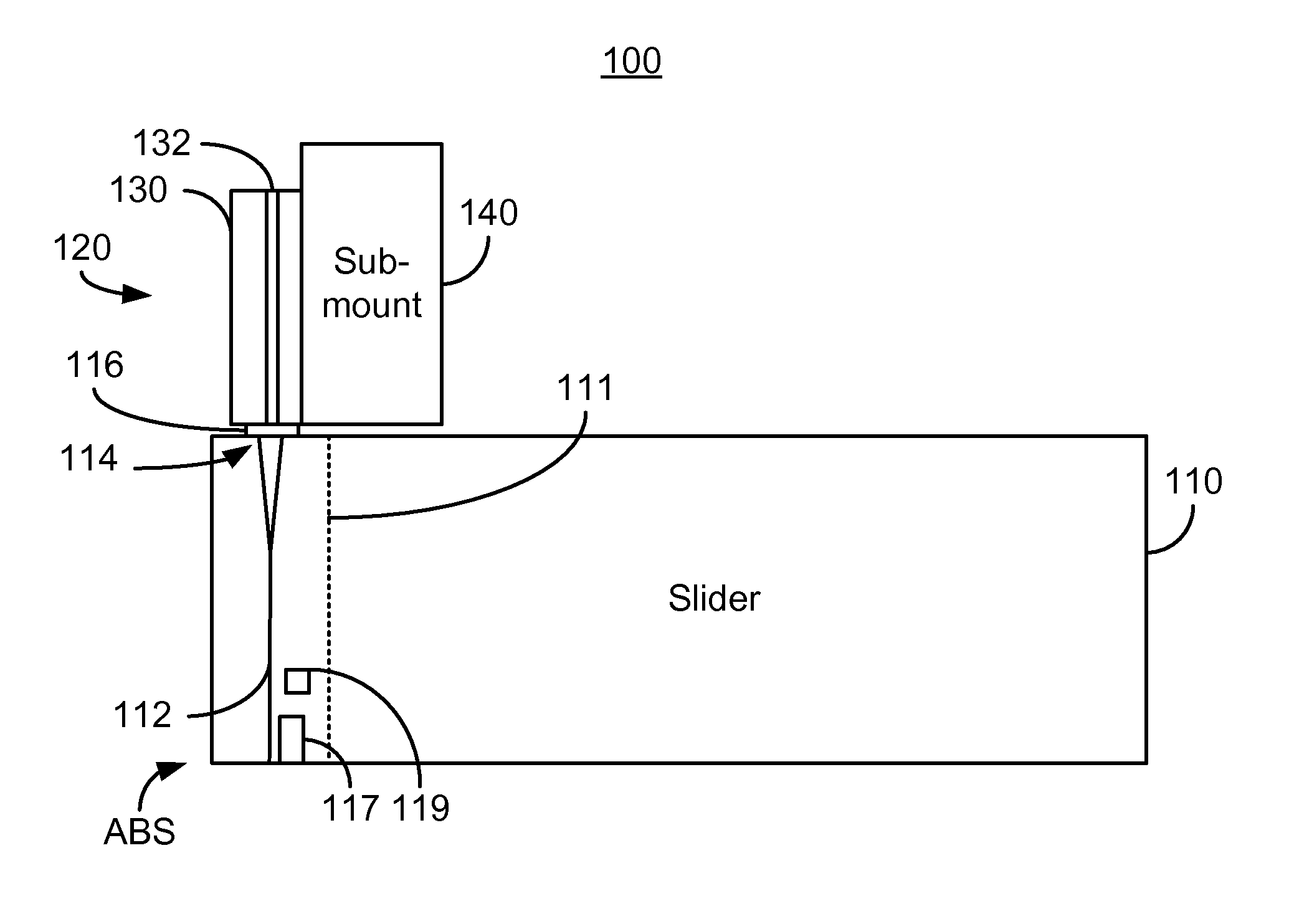
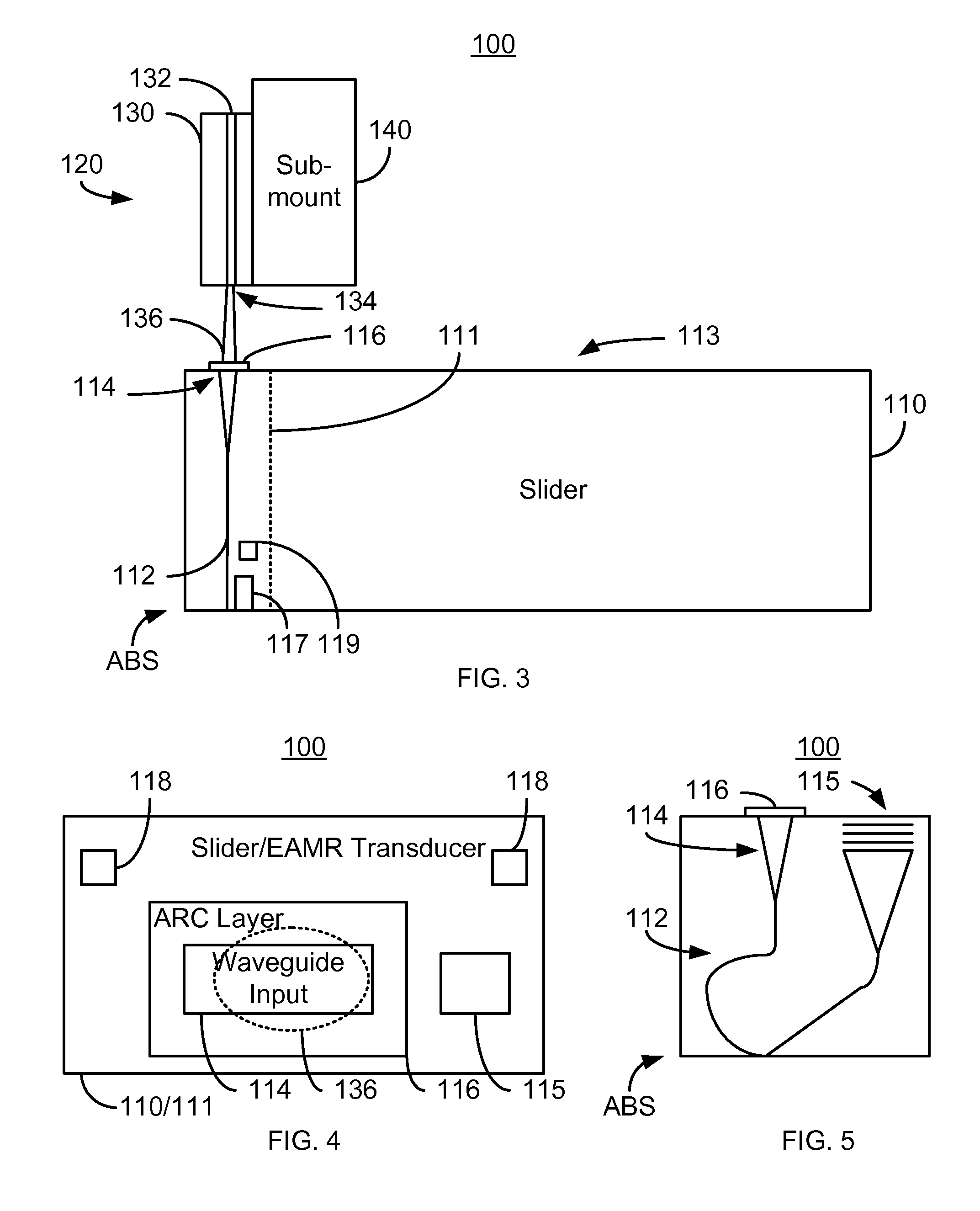
[0015]FIGS. 3-6 depict an exemplary embodiment of an EAMR disk drive 100. For clarity, FIGS. 3-6 are not to scale. For simplicity not all portions of the EAMR disk drive 100 are shown. Although the EAMR disk drive 100 is depicted in the context of particular components other and / or different components may be used. Further, the arrangement of components may vary in different embodiments. FIGS. 3 and 6 are side views of the EAMR disk drive 100 during and after, respectively, alignment of components. The EAMR disk drive 100 includes a slider 110, a media (not shown) such as a disk and a laser assembly 120. In FIG. 3, the laser assembly 120 is separated from the slider by a certain distance. In FIG. 6, the laser assembly 120 has been affixed to the slider 110.

[0016]The laser assembly 120 includes a laser diode 130 and a laser sub-mount 140. The laser diode 130 includes a laser cavity 132 and emission exit 134. Laser light is generated in the laser cavity 132 and is output via the emiss...


PUM

PropertyMeasurementUnit
diameteraaaaaaaaaa
diameteraaaaaaaaaa
sizeaaaaaaaaaa

Abstract

An EAMR disk drive includes a media, a laser, and a slider coupled with the laser. The laser for provides energy. The slider has an air-bearing surface, a laser input side, an EAMR transducer and an antireflective coating (ARC) layer occupying a portion of the laser input side. The ARC layer is configured to reduce back reflections of the energy. The EAMR transducer includes a write pole, a waveguide optically coupled with the laser and at least one coil. The waveguide has a waveguide input. A portion of the ARC layer resides between the laser and the waveguide input. A method aligns the laser to the ARC layer, and then aligns the laser to the waveguide input. The laser may then be coupled to the slider.

Description

BACKGROUND[0001]In fabricating disk drives, such as energy assisted magnetic recording (EAMR) disk drives, it may be necessary to align and bond components. For example, in conventional EAMR disk drives, a laser provides energy used to heat the media for magnetic recording. The laser typically takes the form of a laser diode. The laser diode may be desired to be aligned with a waveguide on the slider and bonded with the slider.[0002]FIG. 1 depicts a conventional method 10 for aligning a conventional laser diode (or substrate on which the laser diode resides) and a slider. FIG. 2 depicts a conventional EAMR head 50 during fabrication using the conventional method 10. FIG. 2 depicts a plan view of the slider 60 and laser 70. The slider 60 and laser 70 include conventional alignment marks 62 and 72, respectively. Also shown are the laser output 74 on the laser and the corresponding laser spot 76 on the slider once alignment has been completed. The slider includes a waveguide 64 which i...

Claims


Application Information

Patent Timeline
Patent Type & Authority Patents(United States)
IPC IPC(8): G11B7/00
CPCG11B5/6088G11B2005/0021
Inventor SHI, ZHONGGOULAKOV, ARKADI B.DEMTCHOUK, ALEXANDRE V.WANG, LEIMORELLI, MICHAEL V.
Owner WESTERN DIGITAL TECH INC
Why Eureka
Try Eureka