Wheel Support Bearing Assembly and Method of Manufacturing the Same

a technology of bearing assembly and wheel support, which is applied in the direction of hubs, mechanical equipment, transportation and packaging, etc., can solve the problems of increasing contact pressure, increasing extra, and reducing the life of the bearing, so as to prevent the detachment of the inner race segment of the finished product, and easy and accurate transportation

Inactive Publication Date: 2009-06-18
NTN CORP
View PDF45 Cites 10 Cited by
  • Summary
  • Abstract
  • Description
  • Claims
  • Application Information

AI Technical Summary

Benefits of technology

[0033]According to the above described method of manufacturing the wheel support bearing assembly, since crimping is carried out to attain a diameter expanded condition by axially pressing the crimping punch, in which the corner between the tapered surface and the front end face is chamfered, axially into the inner peripheral surface of the inboard end portion of the hub axle, interference between the crimping punch and the hub axle can be avoided and the diameter expansion and the crimping process can easily and accurately be carried to a required decree of processing. Also, a press work can be accomplished stably at all time so that the radial expansion of the plastically deformed portion and the height of the projection can be constant, ensuring a prevention of the inner race segment detachment of a completed product.

Problems solved by technology

(1) Since the plastically deformed portion 29b in the hub axle 29 is large in size, the stepped area 36 formed in the inboard end portion of the inner race segment 30 must have a large radial step (of a size having a radial difference of, for example, about 5 to 7 mm). If the size of the stepped area 36 is so large as described above, the surface area of the inboard end face 30a of the inner race segment 30 decreases correspondingly, resulting in an increase of the contact pressure between it and the shoulder 33b of the constant velocity universal joint outer race 33. For this reason, the known wheel support bearing assembly of the structure discussed above, when used in an actual automotive vehicle, tend to involve a cause of frictional wear and / or abnormal noises.
(2) If an attempt is made to accommodate the plastically deformed portion 29b in the hub axle 29 at a location axially inwardly of the inboard end of the inner race segment 30, the stepped area 36 in the inner race segment 30 must have an increased axial length (for example, about 7 to 8 mm). The use of the stepped area 36 in the inner race segment of the increased axial length may result in a tendency of the inner race stepped area 36 to assume a position on a linear line defining the angle of contact of the rolling elements and, therefore, there is the possibility that the lifetime will be reduced as a result of a considerable deformation of the inner race segment under the influence of a load imposed during the operation. The use of the inner race stepped area 36 of the increased axial length may also result in a reduction of the length (surface area), over which the inner race segment 30 is engaged on the hub axle 29, by a quantity corresponding to that reduced and, accordingly, the lifetime of the wheel support bearing assembly may be reduced as a result of occurrence of a creepage in the inner race segment. Although those problems can be resolved if the axial length of the inner race segment is increased, the increase of the axial length of the inner race segment may result in a requirement to increase an extra space in the axial direction.
(3) In addition, since the plastically deformed portion 29b in the hub axle 29 is large in size, a crimping punch may interfere with the inner race segment 30 during the orbital forging to such an extent as to result in a difficulty in processing.

Method used


Image

  • Wheel Support Bearing Assembly and Method of Manufacturing the Same
  • Wheel Support Bearing Assembly and Method of Manufacturing the Same
  • Wheel Support Bearing Assembly and Method of Manufacturing the Same

Examples


Embodiment Construction

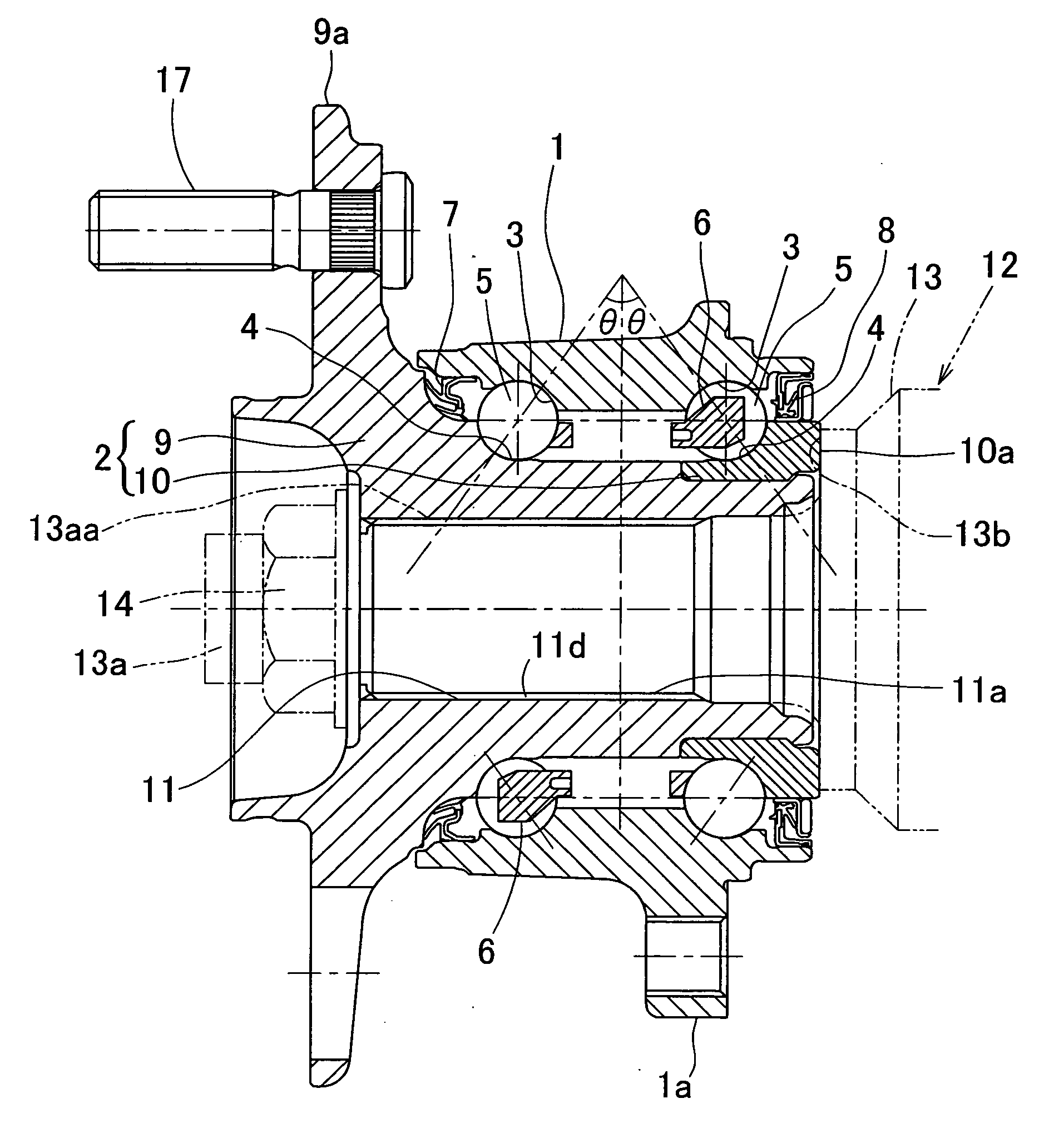
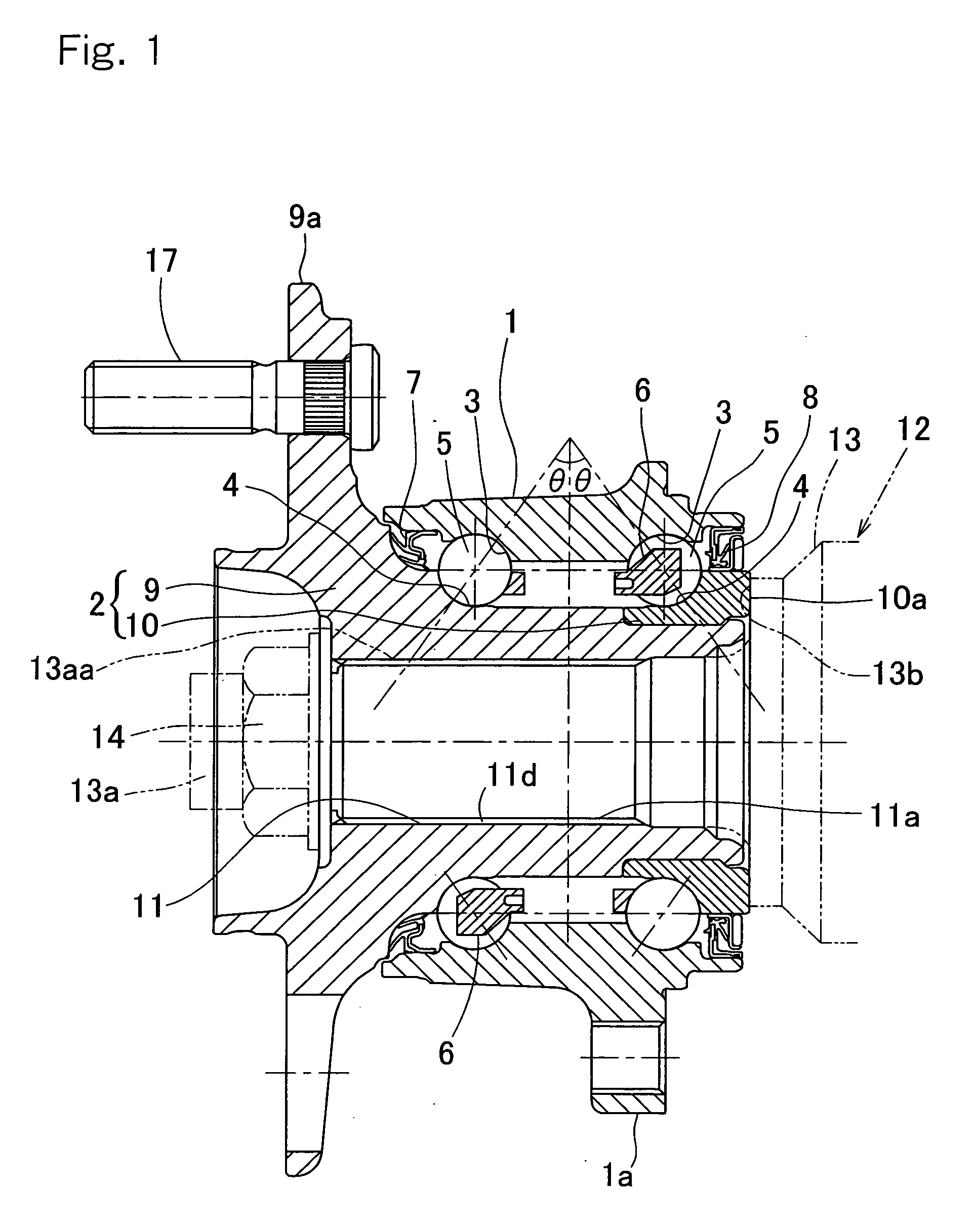
[0061]A first preferred embodiment of the present invention will be described in detail with particular reference to FIGS. 1 to 3. This embodiment is applied to a wheel support bearing assembly for rotatably supporting a vehicle drive wheel, which is an inner race segment rotating model of a third generation type. It is to be noted that in the specification herein presented, the term “outboard” is intended to mean one side of an automotive vehicle body away from the longitudinal center of the automotive vehicle body, whereas the term “inboard” is intended to mean the opposite side of the automotive vehicle body close towards the longitudinal center of the automotive vehicle body.

[0062]The illustrated wheel support bearing assembly includes an outer member 1 having an inner periphery formed with a double row of raceway surfaces 3, an inner member 2 having raceway surfaces 4 formed therein and opposite to those raceway surfaces 3, and a double row of ball-shaped rolling elements 5 int...


PUM

PropertyMeasurementUnit
sizeaaaaaaaaaa
axial lengthaaaaaaaaaa
crimping forceaaaaaaaaaa

Abstract

To provide a wheel support bearing assembly, which is effective to avoid an inner race detachment during assemblage onto an automotive vehicle. The assembly is provided with an inner member made up of a hub axle and an inner race mounted on an outer periphery of an inboard end portion of the hub axle. The inner race has an inner periphery provided with an stepped area that extends to an inboard annular face of the inner race and has a depth measured at an inner peripheral edge of an inboard annular face, and an inner surface of this stepped area is of a shape made up of a straight area and an inclined surface continued from an outboard end of the straight area to the inner peripheral surface, and a plastically deformed portion engageable with the inclined surface as a result of crimping is provided in the hub axle.

Description

BACKGROUND OF INVENTION[0001]1. Field of the Invention[0002]The present invention relates to a wheel support bearing assembly for rotatably supporting a vehicle wheel such as used in, for example, an automotive vehicle and a method of manufacturing such wheel support bearing assembly.[0003]2. Description of the Prior Art[0004]The wheel support bearing assembly for the support of a vehicle drive wheel of a structure shown in FIG. 18 has hitherto been suggested. See, for example, the Japanese Laid-open Patent Publication No. 09-164803. This known wheel support bearing assembly includes double rows of ball-shaped rolling elements 25 operatively interposed between raceway surfaces 23 defined in an outer member 21 and raceway surfaces 24 defined in an inner member 22, respectively. The inner member 22 referred to above is comprised of a hub axle 29, having an outer periphery formed with a radially outwardly extending hub flange 29a for the support of the vehicle wheel, and an inner race ...

Claims


Application Information

Patent Timeline
Patent Type & Authority Applications(United States)
IPC IPC(8): F16C33/46B21D53/10
CPCB60B27/00B60B27/0005B60B27/0084Y10T29/49686F16C19/186F16C43/04Y10T29/49647B60B27/0094F16C33/586F16C2326/02
Inventor KUBOTA, KAZUNORIKOMORI, KAZUOMATSUNAGA, HIROSHIFUJIMURA, AKIRAHASHIMOTO, TETSUYAKIUCHI, MASAHIRO
Owner NTN CORP
Why Eureka
Try Eureka