Cutting insert and tool for chip removing machining

Active Publication Date: 2009-06-18
SECO TOOLS AB
View PDF7 Cites 65 Cited by
  • Summary
  • Abstract
  • Description
  • Claims
  • Application Information

AI Technical Summary

Benefits of technology

[0005]It is also desirable to provide the cutting insert with clearances between the cutting

Problems solved by technology

This means that only four cutting corners can be utilized in. one and the same mill

Method used


Image

  • Cutting insert and tool for chip removing machining
  • Cutting insert and tool for chip removing machining
  • Cutting insert and tool for chip removing machining

Examples


Embodiment Construction

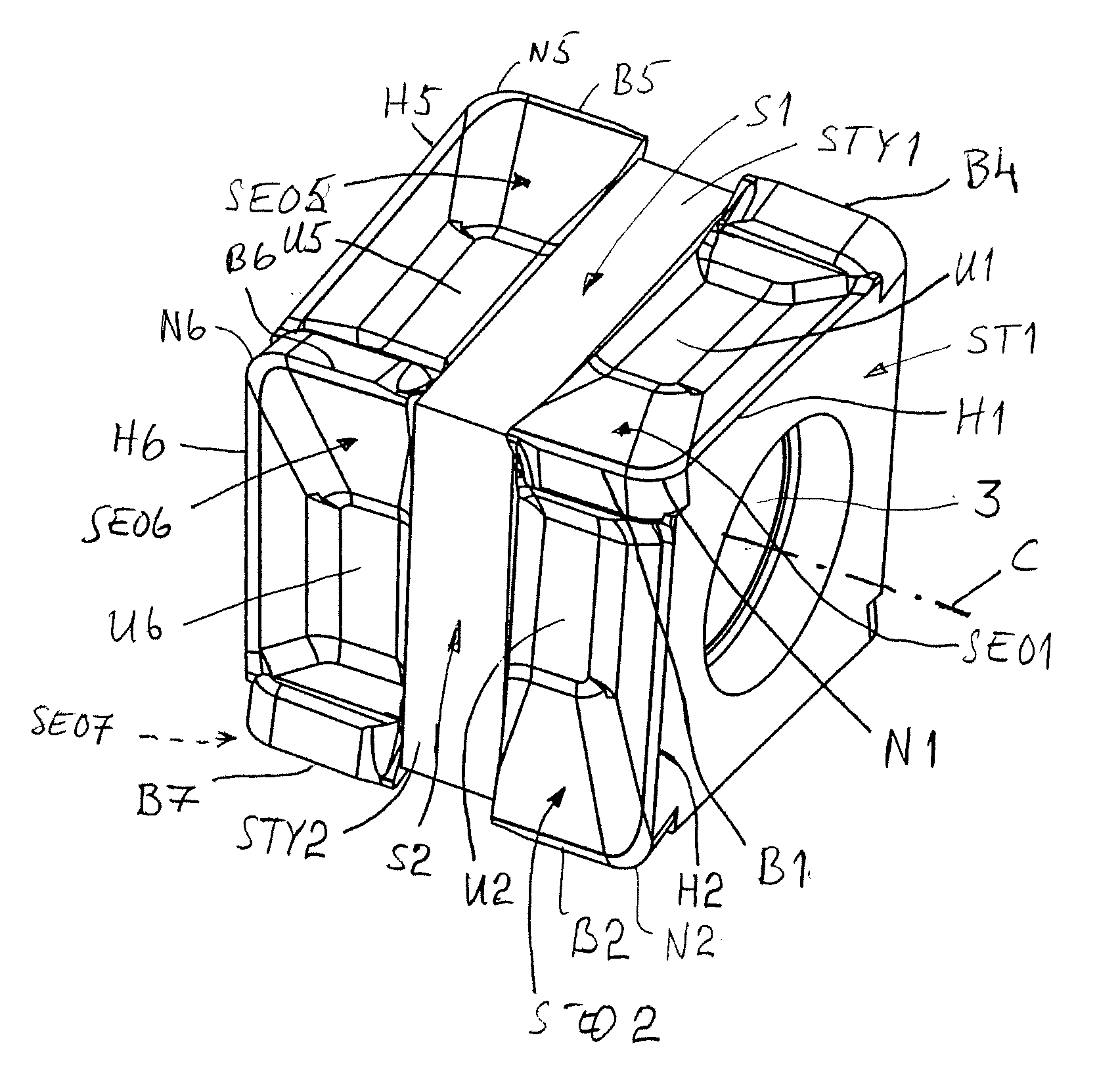
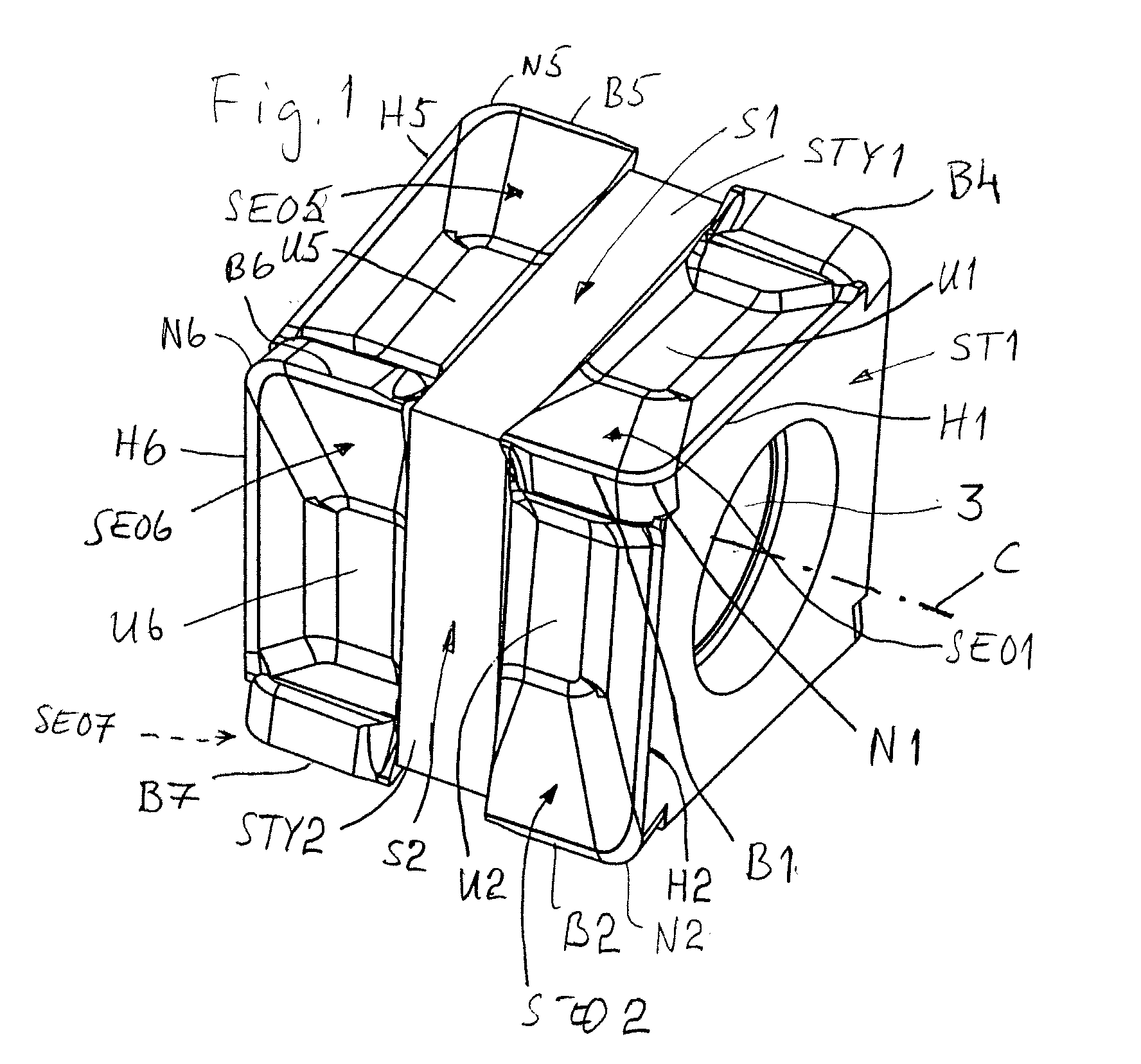
[0019]The cutting insert 1 for chip removing machining shown in FIG. 1 constitutes a milling insert, which is four-sided, i.e., it has four active sides. The cutting insert 1 has a parallelepipedic basic shape and is manufactured from pressed or injection moulded cemented carbide. With “cemented carbide”, reference is here made to WC, TiC, TaC, NbC etc., in sintered combination with a binder metal such as, for instance, Co or Ni. The cutting insert 1 is preferably at least partly covered with a layer of, e.g., Al203, TiN and / or TiCN. In certain cases, it may be justified that the cutting edges comprise or consist of soldered superhard materials such as CBN or PCD.

[0020]As is seen in FIG. 1, the cutting insert 1 comprises four sides S1, S2, S3, S4, which are intended for chip removing machining. In FIG. 1, only two sides S1 and S2 are visible. The cutting insert 1 has also two opposite support sides ST1 and ST2, which are parallel with each other. Only the first support side ST1 is v...


PUM

PropertyMeasurementUnit
Angleaaaaaaaaaa
Shapeaaaaaaaaaa
Radiusaaaaaaaaaa

Abstract

An indexable milling insert has a parallelepipedic shape. The cutting insert includes a mounting hole placed centrally in the cutting insert, a first support side and a second support side, which support sides are parallel with each other and act as alternating support sides. The cutting insert is provided with main cutting edges, which are orientated perpendicularly to the centre axis of the mounting hole as well as provided in such a way that a rotation of the cutting insert around the centre axis of the mounting hole to an alternative insert seat alternatively a turning of the cutting insert to an alternative insert seat provides an identical location of the main cutting edges in relation to a piece to be machined. A milling tool equipped with such milling inserts is also provided. The cutting insert can include four identical sides for chip removing machining, the sides extending between the parallel support sides, and each side has exactly two cutting edge areas.

Description

BACKGROUND AND SUMMARY[0001]The present invention relates to a cutting insert and a tool for chip removing machining, especially a milling insert and a milling tool. The milling insert is indexable in the milling tool. The milling tool is an end mill having 90° setting angle.[0002]By each one of WO 2003 / 101655 and WO 2004 / 050283, a tangential cutting insert as well as a milling tool are previously known. The cutting inserts comprise four cutting corners, which are distributed on two sides for chip removing machining, i.e., each side has two cutting corners.[0003]WO / 0002693 shows a milling system having tangentially mounted cutting inserts where each cutting insert has eight cutting corners, which are distributed on two sides for chip removing machining, i.e., each side has four cutting corners. However, four of these cutting corners are intended for clockwise rotary machining and four cutting corners are intended for anticlockwise rotary machining. This means that only four cutting ...

Claims


Application Information

Patent Timeline
IPC IPC(8): B23C5/02B23C5/20B23C5/22
CPCB23C5/06B23C5/202B23C2200/085B23C2200/201B23C2200/367B23C2210/207Y10T407/2274Y10T407/1936Y10T407/192Y10T407/1924Y10T407/2268Y10T407/23Y10T407/235B23B27/1607B23B27/16B23C5/20
Inventor JANSSON, MIKAEL
Owner SECO TOOLS AB
Why Eureka
Try Eureka