Tooth implant with a primary and a secondary crown

a tooth implant and secondary crown technology, applied in the field of tooth implants, can solve the problems of relatively large length and relatively complicated design, and achieve the effect of preventing cogging of the prosthesis or the bridge during the installation

Inactive Publication Date: 2009-06-18
ACCURA HLDG
View PDF9 Cites 14 Cited by
  • Summary
  • Abstract
  • Description
  • Claims
  • Application Information

AI Technical Summary

Benefits of technology

[0008]The tooth implant according to the invention comprises two implant parts in the form of a primary and a secondary crown which are to be joined. On the secondary crown, a prosthesis or bridge is mounted wherein the outer surface of the secondary crown, which carries the prosthesis or bridge, is in at least one cross-sectional plane almost, or essentially, circular or, respectively, partially circular and is accommodated in a corresponding support cavity of the prosthesis or, respectively, a cover structure in a pivotal manner. In this way, a certain pivotability of the secondary crown with respect to the prosthesis or, respectively, the bridge is obtained, whereby an additional degree of freedom or respectively, movement capability is provided and the secondary crown can be adjusted angularly depending on the anatomical conditions with respect to the longitudinal axis of the tooth implant. In this way, the implant installation can be improved in a functional as well as technical respect.
[0009]The partially circular or spherical shape of the outer surface of the secondary crown and the complementary support structure in the prosthesis or the cover structure provides for an additional joint which is obtained by simple design features. The support structure is established by a cavity formed in the prosthesis or, respectively, the cover structure and accommodating the partially circular or spherical outer surface of the secondary crown. This arrangement is of a particularly simple design.
[0010]In accordance with a preferred further development, the outer surface of the secondary crown is ball-shaped or at least partially ball-shaped and pivotally accommodated in a correspondingly complementary support structure in the prosthesis or respectively, bridge or cover structure. The partially ball-shaped structure is to be understood to be a three-dimensional embodiment of the partially circular structure whereby not only one but altogether two additional rotational degrees of freedom of motion in different spatial directions are obtained. The secondary crown is, as a result, supported so as to be pivotable with respect to the prosthesis or, respectively, the bridge in two pivot directions. In this way, additional adjustment possibilities for the secondary crown with respect to the prosthesis or, respectively, the bridge are obtained. As a result of the adjustability, it is possible for the secondary crown to accommodate adjustment movements during its installation or its removal to avoid cogging of the secondary crown with the respective primary crown. This is particularly true when several implants with primary and secondary crowns are involved which have diverging axes. The advantage or respectively, possible embodiments in connection with the circular embodiments mentioned above also apply to the ball- or partially ball-shaped embodiments.
[0012]The secondary crown may be accommodated at least essentially without play in the support structure of the prosthesis or, respectively, the cover or bridge in order to prevent an undesirable wiggling of the prosthesis or the bridge. It is however possible that a certain play-fit is desired, in order to transmit chewing forces to a greater extent via the prosthesis to the jaw gum surface with a certain resiliency.
[0013]In a further advantageous embodiment, the secondary crown is provided with a projection which projects from the outer surface thereof with a certain play into a cavity formed in the support structure of the cover or the prosthesis or bridge. With such room for movement, the secondary crown can pivot slightly in the given degrees of freedom with respect to the prosthesis or, respectively the bridge. However, the pivot movement is limited by an abutment of the projection of the outer surface of the secondary crown on the side walls of the recess in the support structure. The stop formed thereby forms an effective simple limit for the relative pivot movement of the secondary crown with respect to the prosthesis or, respectively, the bridge.
[0016]In accordance with an advantageous further embodiment, the ball-shaped section of the primary crown which extends into the complementarily formed recess in the secondary crown is elastically resilient, so that the ball-shaped section can be inserted into the recess also if the recess extends over an angular range >180° and, as a result, forms an undercut. Because of the elasticity, the ball-shaped section of the primary crown can be compressed and inserted into the correspondingly shaped recess in the secondary crown. After insertion, the ball-shaped section assumes again its original shape whereby a form-locking connection between the primary and the secondary crown is established. Vice versa, the recess walls may be elastically resilient. Because of the elasticity the hollow ball-shaped recess of the secondary crown can be expanded and the ball-shaped section of the primary crown can be inserted. After insertion, the hollow ball-shaped recess of the secondary crown resumes, its original shape whereby a form-locking connection between the primary and the secondary crown is established.

Problems solved by technology

It is however a disadvantage that the design is relatively complicated and extends over a relatively large length in axial direction.

Method used


Image

  • Tooth implant with a primary and a secondary crown
  • Tooth implant with a primary and a secondary crown
  • Tooth implant with a primary and a secondary crown

Examples


Embodiment Construction

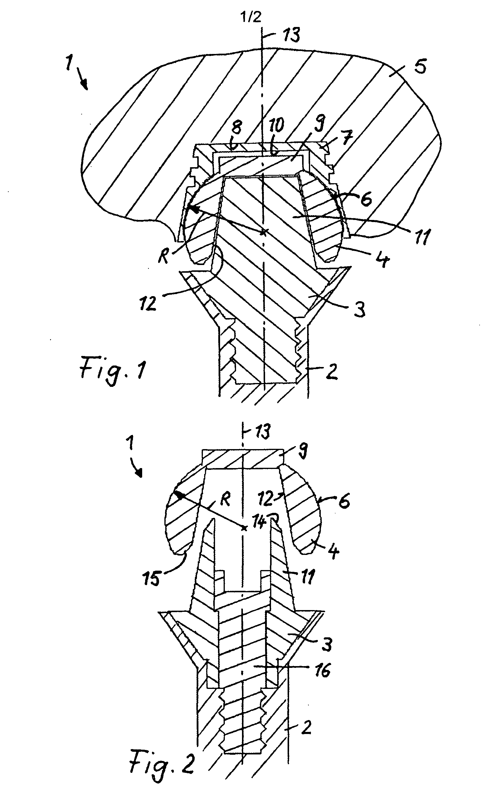
[0023]In the figures functionally identical parts are identified by the same reference numerals.

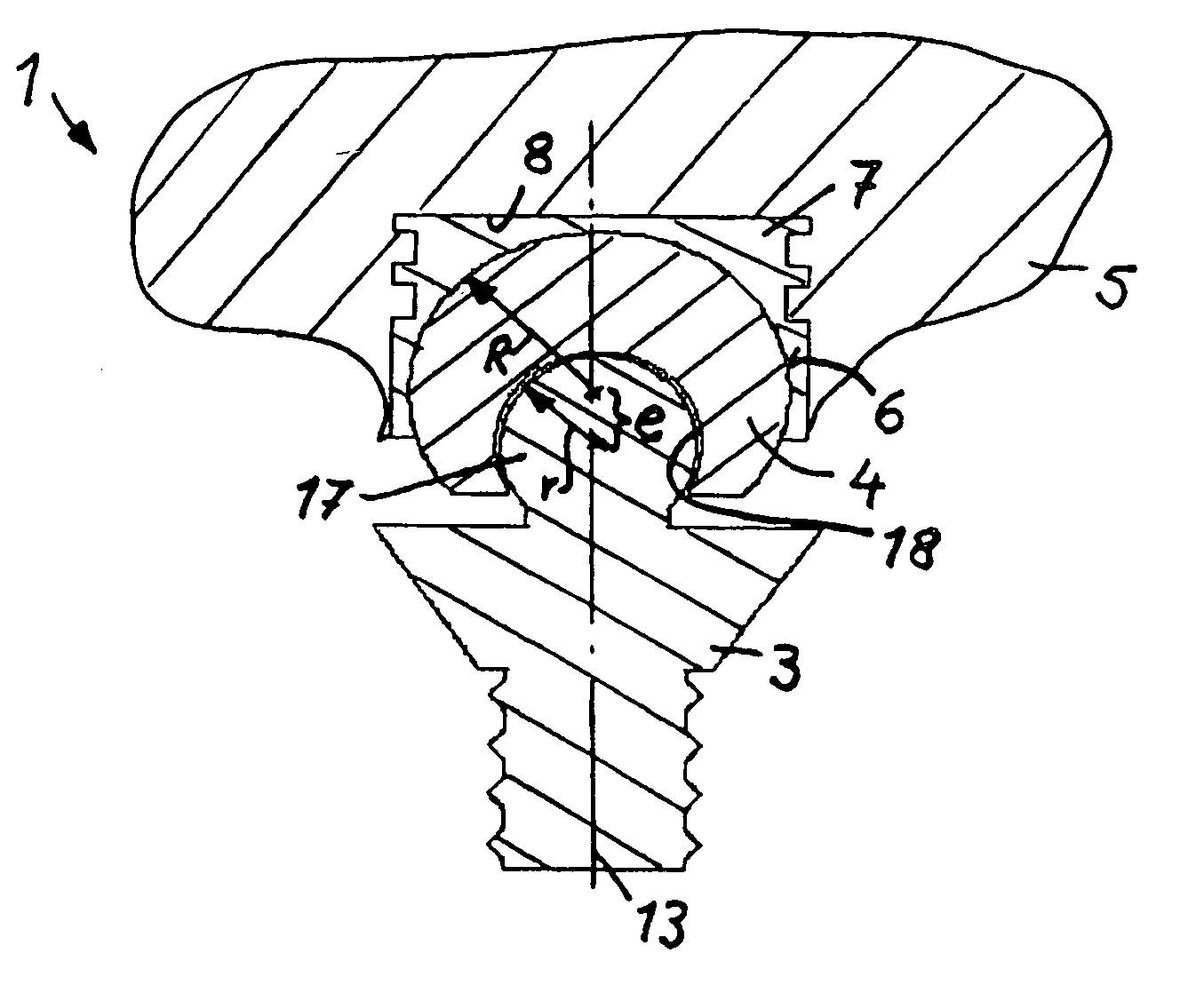
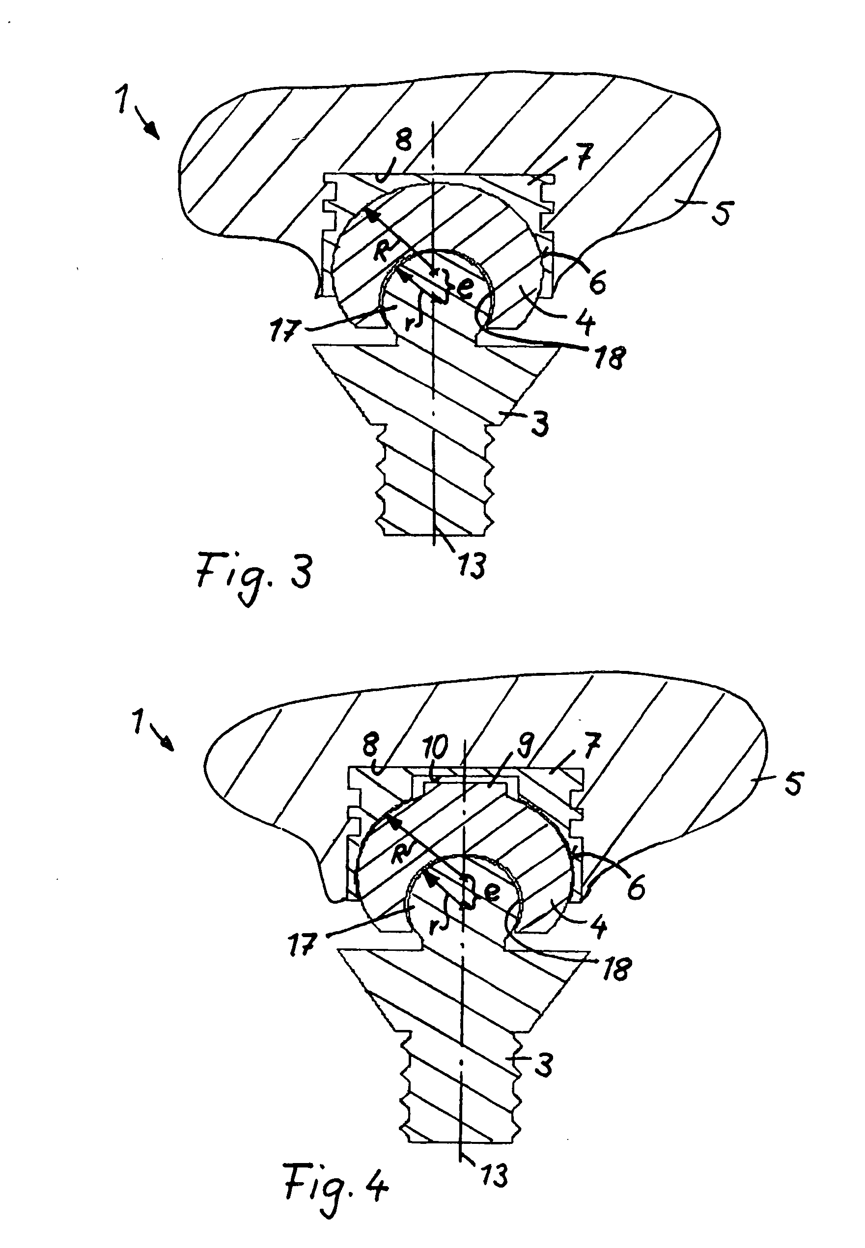
[0024]The tooth implant 1 as shown in FIG. 1 comprises a base carrier 2, which is to be anchored in the jaw of a patient, a primary crown 3 screwed into the base carrier 2, a secondary crown 4 connected to the primary crown 3 and a prosthesis 5 or bridge or similar structure disposed on the secondary crown 4. The screw connection between the base carrier 2 and the primary crown 3 is obtained by an internal thread provided in the base carrier 2 and an external thread provided on the primary crown 3 and threaded into the internal thread of the base carrier. The connection between the primary crown 3 and the secondary crown 4 is established by way of a cone section 11 projecting from the primary crown 3 into a complementarily shaped accommodation recess 12 formed into the secondary crown 4. Between the cone section 11 and the wall of the accommodation recess 12, a frictional engagement is to...


PUM


Abstract

In a tooth implant comprising a primary crown for mounting on a base carrier implanted into a patient's jaw and a secondary crown mounted onto the primary crown for supporting a bridge or prosthesis, the primary crown has a circular or ball-shaped projection and the secondary crown has a recess of a complementary configuration receiving the projection of the primary crown so that the secondary crown is pivotally supported by the primary crown for permitting adjustments during installation of the prosthesis or bridge onto the secondary crown.

Description

[0001]This is a Continuation-In-Part Application of pending International Patent Application PCT / EP2007 / 006920 filed Aug. 6, 2007 and claiming the priority of German patent application 10 2006 08 395.8 filed Aug. 15, 2006.BACKGROUND OF THE INVENTION[0002]The invention relates to a tooth implant with two implant parts comprising a primary and a secondary crown which are interconnected and of which the secondary crown is adapted to support a tooth prosthesis or a bridge and has in at least one cross-sectional plane an at least partially circular shape for pivotally supporting the prosthesis or the bridge.[0003]DE 10 2004 018 512 A1 discloses such a tooth implant wherein a base carrier is to be implanted into the jaw of a patient and a primary crown is mounted onto the base carrier for example by a screw connection. Onto the primary crown, which is cone-shaped, a secondary crown is placed so as to form a support structure for a prosthesis or a bridge. The connection between the primary...

Claims


Application Information

Patent Timeline
Patent Type & Authority Applications(United States)
IPC IPC(8): A61C8/00A61C5/73
CPCA61C8/005A61C13/2656A61C8/0069A61C8/0053
Inventor LAUX, ROBERT
Owner ACCURA HLDG
Why Eureka
Try Eureka