Detecting apparatus and method of robot cleaner

a robot cleaner and detection apparatus technology, applied in the field of robot cleaners, can solve the problems of large measurement deviation at the receiving unit, difficult to accurately measure distance from the floor, and inability to detect both the drop-off and the bump on the floor, so as to reduce the measurement deviation

Active Publication Date: 2009-06-18
LG ELECTRONICS INC
View PDF5 Cites 10 Cited by
  • Summary
  • Abstract
  • Description
  • Claims
  • Application Information

AI Technical Summary

Benefits of technology

[0011]Therefore, in order to solve such problems, an object of the present invention is to provide a detecting apparatus of a robot cleaner capable of reducing a measurement deviation between a transmitting unit and a receiving unit.
[0013]Still another object of the present invention is to provide a detecting apparatus of a robot cleaner capable of ensuring a required amount of light when an amount of light received at a receiving side is not adequate.
[0017]In yet another aspect of the present invention, there is provided a detecting method of a robot cleaner, for detecting a floor on which the robot cleaner moves. The method including, a floor detecting step of sending a signal from a transmitting unit a signal for detecting the floor and receiving a signal at a receiving unit which is sent from the transmitting unit to be then reflected on the floor. An optic angle adjusting step of adjusting an optic angle by an optical angle adjusting unit of at least one of the sent signal and the received signal, and a light shielding step of partially shielding a signal sent through the optic angle adjusting unit so as to reduce a deviation of each of the sent signal and the received signal.
[0019]The detecting method may further include a step of preventing a spread of at least one of the sent signal and the received signal, and inducing an ongoing direction thereof.

Problems solved by technology

In particular, the light tail may become longer according to detected color and feel of the floor, which causes a great measurement deviation at the receiving unit.
As a result, it may be difficult to accurately measure distance from the floor.
Hence, the robot cleaner according to the related art, which uses the on / off type infrared sensor having a constantly fixed measurement distance, cannot detect different distances, so that it cannot detect both the drop-off and the bump existing on the floor.
Accordingly, due to the drop-off or bump not detected, errors may occur during the travel of the robot cleaner.
Furthermore, there may occur a case where a required amount of light is not received by the receiving unit due to color and texture of the floor.
For example, in case of a black floor, the receiving unit may be able to receive a small amount of light, thereby making a smooth measurement difficult.

Method used


Image

  • Detecting apparatus and method of robot cleaner
  • Detecting apparatus and method of robot cleaner
  • Detecting apparatus and method of robot cleaner

Examples


first embodiment

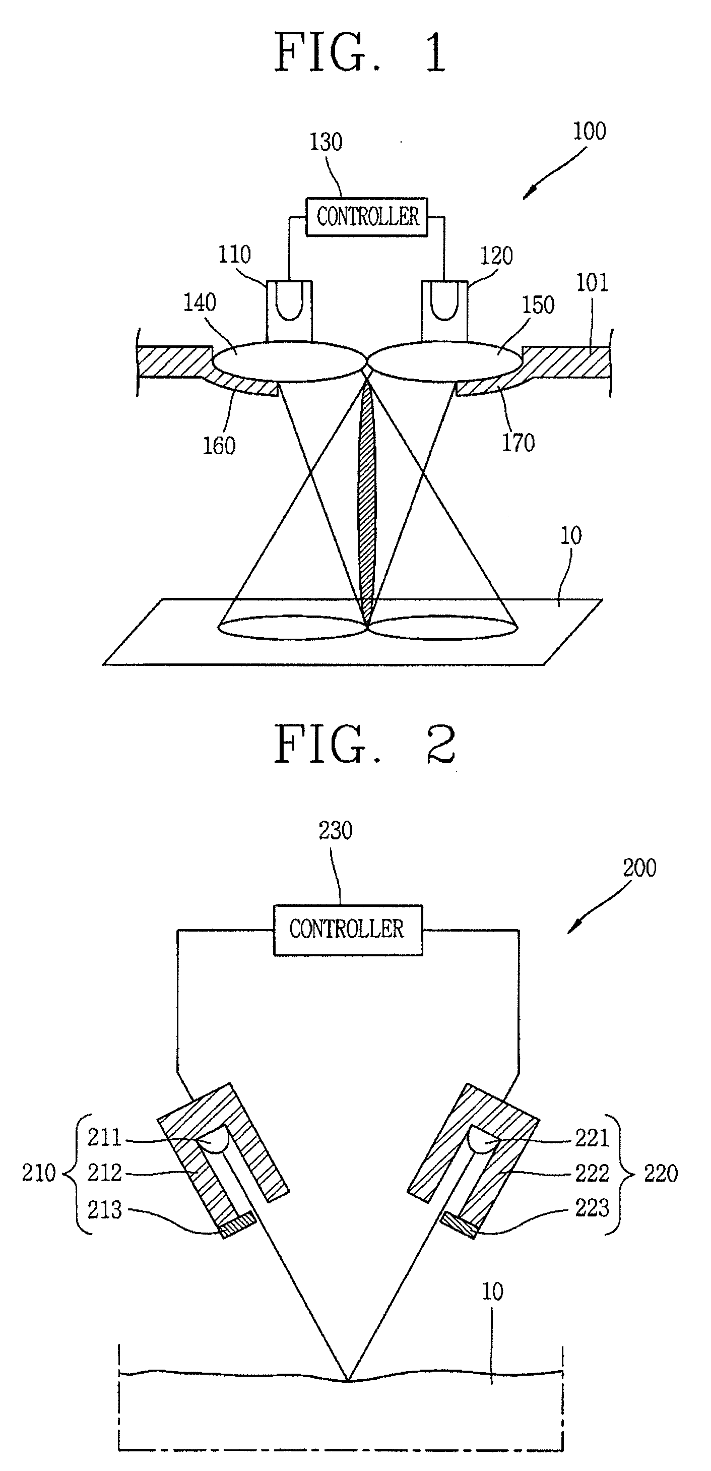
[0039]FIG. 1 is a schematic view showing a detecting apparatus of a robot cleaner in accordance with the present invention.

[0040]As shown in FIG. 1, a detecting apparatus 100 of a robot cleaner in accordance with a first embodiment of the present invention may include a detecting sensor having a transmitting unit 110 and a receiving unit 120, a controller 130, a transmitting side lens 140, a receiving side lens 150, a transmitting side light shielding unit 160, and a receiving side light shielding unit 170.

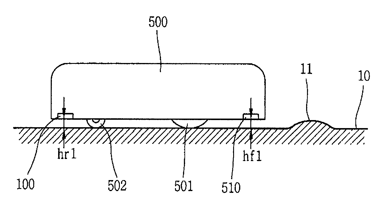
[0041]A reference numeral 10 denotes a floor on which the robot cleaner travels, and 101 denotes a casing of the robot cleaner.

[0042]The transmitting unit 110 is configured to transmit a signal for detecting the floor 10, and the receiving unit 120 is configured to receive a signal which is sent from the transmitting unit 110 and then reflected on the floor 10.

[0043]An infrared sensor for transmitting and receiving infrared rays may be used as the transmitting unit 110 and the rec...

second embodiment

[0057]FIG. 2 is a schematic view showing a detecting apparatus of a robot cleaner in accordance with the present invention.

[0058]As shown in FIG. 2, a detecting apparatus 200 of a robot cleaner according to a second embodiment of the present invention may include a transmitting unit 210, a receiving unit 220 and a controller 230, thus to detect the floor 10.

[0059]The transmitting unit 210 is provided with a light transmitter 211, a transmitting side light inducing portion 212 and a transmitting side light shielding portion 213. The receiving unit 220 is provided with a light receiver 221, a receiving side light inducing portion 222 and a receiving side light shielding portion 223.

[0060]The light transmitter 211 outputs infrared light. Such infrared light emitted from the light transmitter 211 is induced toward the floor 10 by the transmitting side light inducing portion 212 formed with a certain length.

[0061]The light reflected on the floor 10 is then introduced into the receiving s...

third embodiment

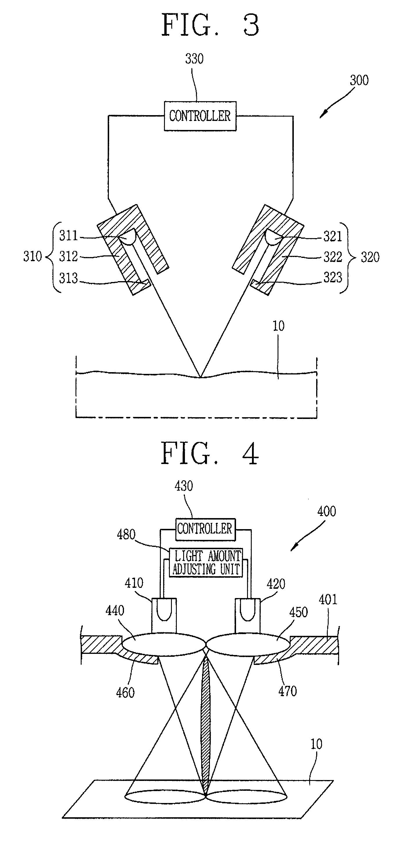
[0066]FIG. 3 is a schematic view showing a detecting apparatus of a robot cleaner in accordance with the present invention.

[0067]As shown in FIG. 3, a detecting apparatus 300 of a robot cleaner according to a third embodiment may include a transmitting unit 310 provided with a light transmitter 311, a transmitting side light inducing portion 312 and a transmitting side light shielding portion 313. A receiving side 320 is provided with a light receiver 321, a receiving side light inducing portion 322 and a receiving side light shielding portion 323, and a controller 330.

[0068]The detecting apparatus 300 having such configuration detects the floor 10, as a detection target, which faces a bottom of the robot cleaner.

[0069]In the third embodiment, the transmitting side light shielding portion 313 and the receiving side light shielding portion 323 are integrally formed with the transmitting side light inducing portion 312 and the receiving side light inducing portion 322, respectively.

[0...


PUM


Abstract

A detecting apparatus and method of a robot cleaner is disclosed. The apparatus includes a detecting unit provided with a transmitting unit for sending a signal to detect the floor and a receiving unit for receiving a signal sent from the transmitting unit to be reflected on the floors an optic angle adjusting unit disposed at least one of the transmitting unit and the receiving unit and configured to adjust optic angles of the signals, and a light shielding unit configured to partially shield a signal sent through the optic angle adjusting unit in order to reduce a deviation of each signal of the transmitting unit and the receiving unit. Accordingly, a measurement deviation with respect to color and feel of the floor can be reduced. Also, an amount of light received at the receiving unit can be obtained as much as required, which allows an accurate detection of the detecting apparatus. In addition, even if there are both drop-off and bump on the floor, the robot cleaner can smoothly operate.

Description

RELATED APPLICATION[0001]The present disclosure relates to subject matter contained in priority Korean Application No. 10-2007-0128486, filed on Dec. 11, 2007, which is herein expressly incorporated by reference in its entirety.BACKGROUND OF THE INVENTION[0002]1. Field of the Invention[0003]The present invention relates to a robot cleaner, and particularly, to a detecting apparatus and method of a robot cleaner, capable of reducing a measurement deviation with respect to color and texture of a floor, improving a detection accuracy by obtaining an amount of light received at a receiving unit as much as being required, and allowing a smooth operation of the robot cleaner even when there are drop-offs and bumps on the floor.[0004]2. Background of the Invention[0005]In the related art) a robot cleaner indicates an automatic cleaner which performs cleaning by itself while moving around on a floor, according to an input program, by using a charged battery as a power source.[0006]Unlike an...

Claims


Application Information

Patent Timeline
Patent Type & Authority Applications(United States)
IPC IPC(8): G05B19/04G06F19/00
CPCG01B11/24A47L9/28A47L9/00A47L11/24
Inventor JUNG, YOUNG-GYUKIM, SANG-CHEONNAH, TAE-WOONGCHOI, WOO-JIN
Owner LG ELECTRONICS INC
Why Eureka
Try Eureka