Truss Semi-Submersible Offshore Floating Structure

a floating structure and semi-submerged technology, applied in the direction of vessel construction, special-purpose vessels, vessel movement reduction by foils, etc., can solve the problems of increased cost, increased fatigue in scrs, and inability to adapt to dry tree riser arrangement, etc., to eliminate deficiencies in the known art and reduce motion

Inactive Publication Date: 2009-06-25
J RAY MCCDERMOTT SA
View PDF4 Cites 6 Cited by
  • Summary
  • Abstract
  • Description
  • Claims
  • Application Information

AI Technical Summary

Benefits of technology

[0010]The present invention addresses the deficiencies in the known art. The hull includes four columns that are supported by two pontoons. The columns support the topsides and the topsides structural framing serves as horizontal framing between the columns. Additional braces may be added between columns and topsides framing as necessary. A truss space frame is attached to the columns. The truss space frame preferably includes heave plates and possibly a keel tank. The truss space frame extends downward below the pontoons a sufficient distance in the water column that minimizes motions caused by wind and wave forces and eliminates the deficiencies in the known art. The hull section integrated with topsides and the truss space frame are constructed separately and assembled together at the offshore site where the structure is used for drilling and / or production.

Problems solved by technology

As a result, it has not been suitable for a dry tree riser arrangement.
Another problem from the large motion of the semi-submersible is that it causes fatigue in the SCRs more easily, which requires more stringent fatigue design for the SCRs and thus costs more.
For a platform in ultra deepwater with large diameter SCRs, the solutions to this problem could become technically or economically unfeasible.
However, the heave motion is still relatively large compared with spars and TLPs.
Also, the dry tree arrangement is still not feasible.
The known designs suffer several deficiencies.
The hull has to be a new build and conversion of an existing semi-submersible hull is not possible.
The extendable columns take too much deck space.
In some cases it could be as much as thirty percent of the total deck space, which is impractical from a topsides equipment layout point of view.
The column-to-deck connections are complicated.
They are hard to build, risky during installation, and difficult to maintain.

Method used


Image

  • Truss Semi-Submersible Offshore Floating Structure
  • Truss Semi-Submersible Offshore Floating Structure
  • Truss Semi-Submersible Offshore Floating Structure

Examples


Embodiment Construction

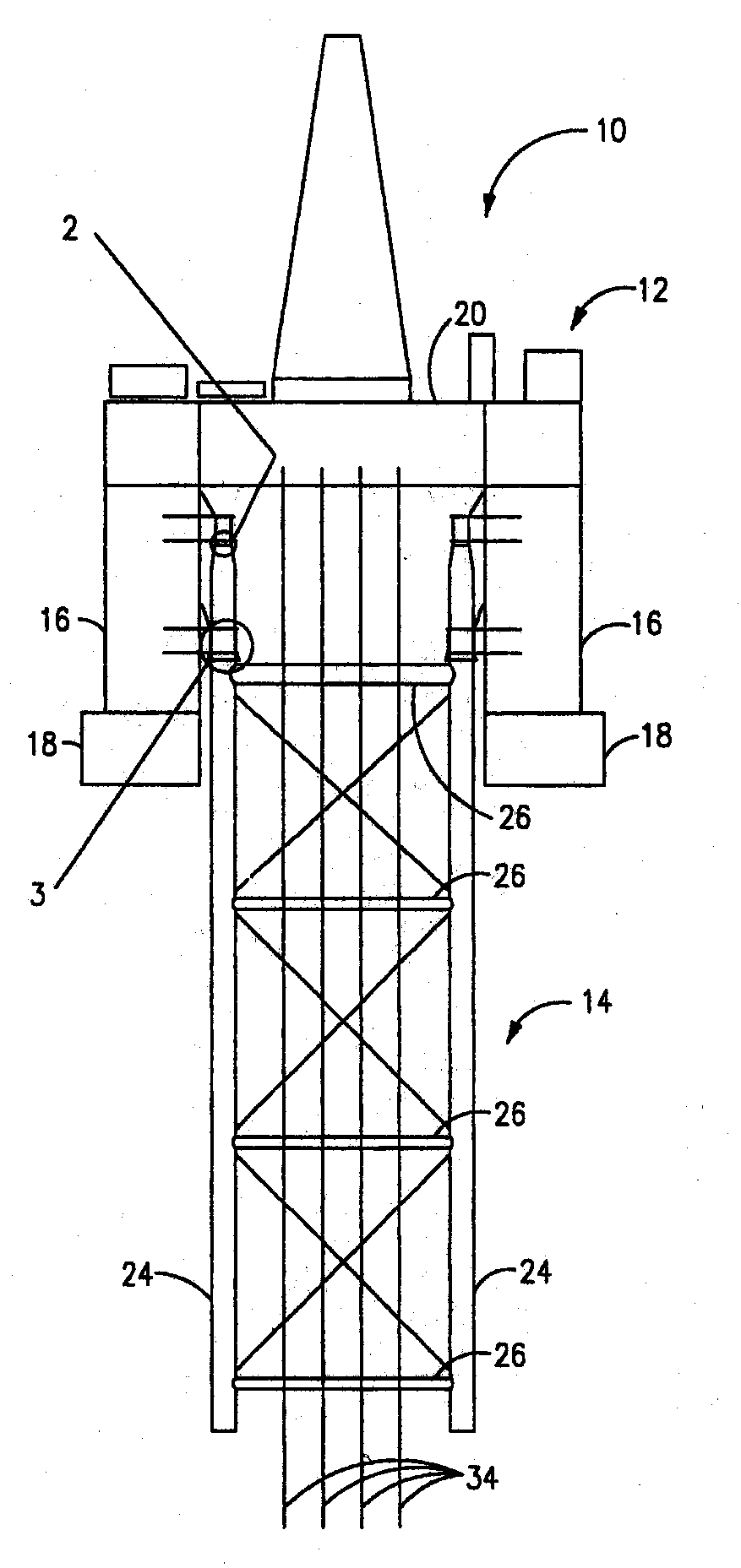
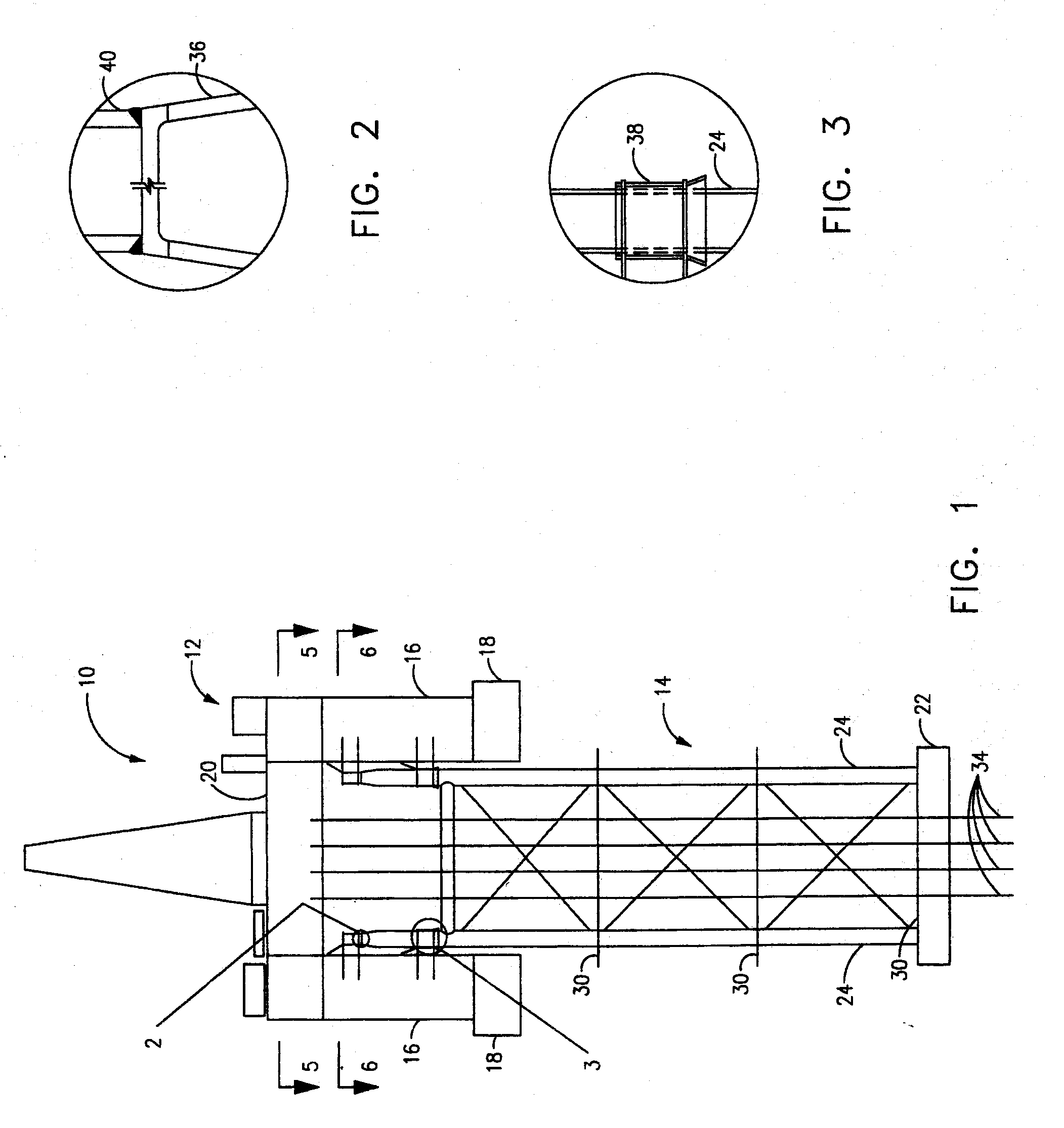
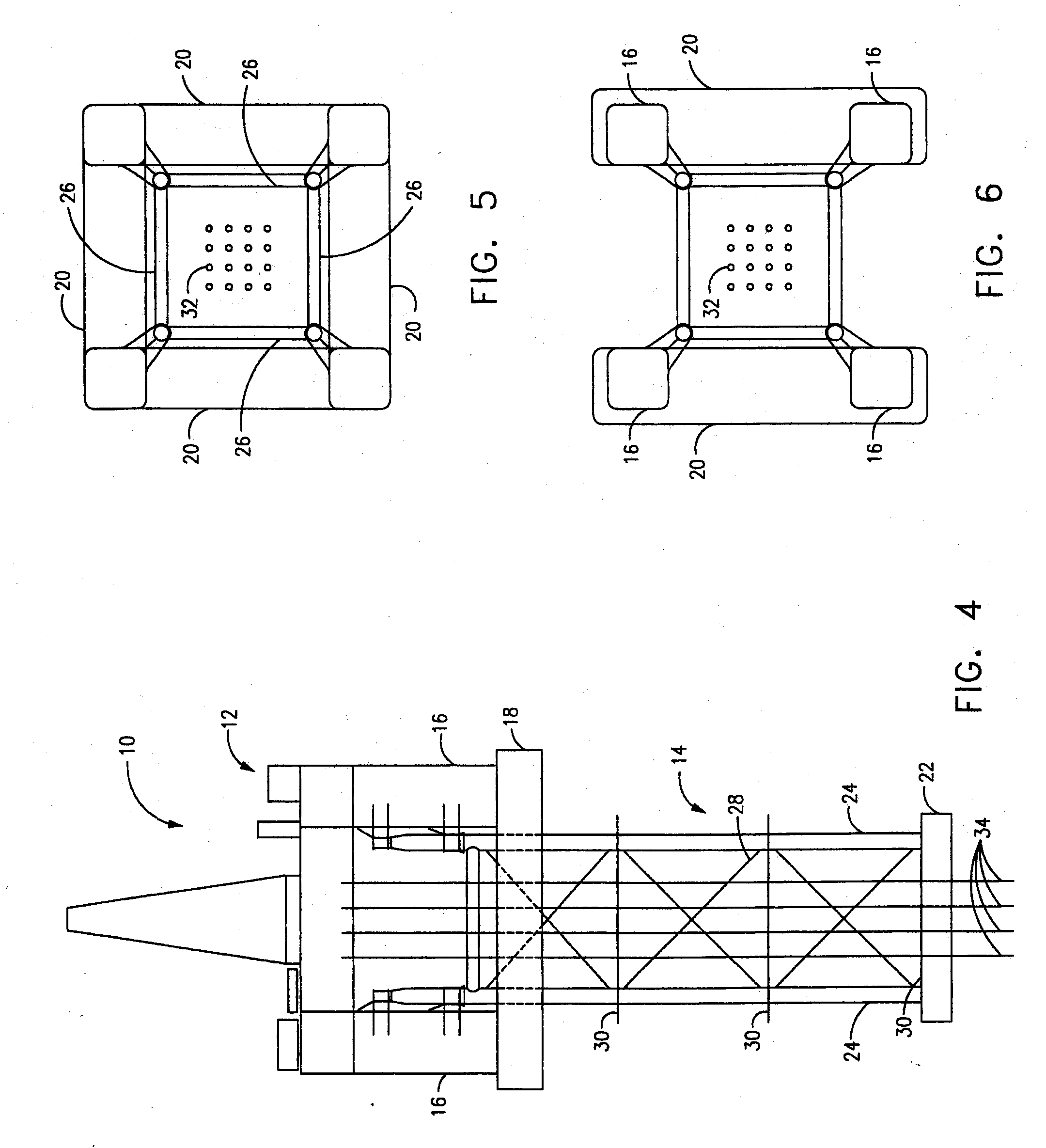
[0021]The invention is generally indicated by numeral 10 in FIGS. 1 and 4. Semi-submersible floating offshore structure 10 is generally comprised of a buoyant hull 12 and a truss frame 14.

[0022]The hull 12 is comprised of four columns 16 that are supported on their lower ends by at least two pontoons 18. The topside structural framing 20 serves as horizontal bracing between the columns 16. The general construction, arrangement, and assembly of the pontoons, columns, and topside structural framing is generally known. Additional braces 42, seen in FIG. 7, may be provided on the hull 12 if desired. For ease of illustration, the braces 42 are only shown in FIG. 7.

[0023]Even though the conventional semi-submersible hull design can be used for the invention, the preferred design is to use pontoons that are larger and deeper and columns that are smaller in cross section. This preferred arrangement will provide better control of motions that have been a source of the above-referenced proble...


PUM


Abstract

A semi-submersible structure. The hull includes four columns that are supported by two pontoons. The columns support the topsides and the topsides structural framing serves as horizontal framing between the columns. A truss frame is attached to the columns. The truss frame preferably includes heave plates. The truss frame extends downward below the pontoons a sufficient distance in the water such that it minimizes motions caused by environmental forces. The hull section and the truss space frame are constructed separately and assembled together at the offshore site where the structure is used for drilling and / or production.

Description

RELATED APPLICATION INFORMATION[0001]This application is a divisional of application Ser. No. 11 / 332,707 filed on Jan. 13, 2006.FIELD AND BACKGROUND OF INVENTION[0002]The invention is generally related to floating offshore structures and more particularly to semi-submersible floating offshore structures.[0003]The semi-submersible is a type of floating structure that has vertical columns supporting topsides and supported on large pontoons. The structure is held in position by the use of spread mooring lines that are anchored to the seafloor. The semi-submersible has a number of unique characteristics compared with other floating structures such as a spar and TLP (tension leg platform). These advantages include: The semi-submersible has good stability because of a large footprint and low center of gravity for the topsides. The hull requires lower steel tonnage. The hull can be a new build or converted from an existing drilling semi. The semi-submersible may include drilling capability...

Claims


Application Information

Patent Timeline
Patent Type & Authority Applications(United States)
IPC IPC(8): B63B35/44
CPCB63B1/04B63B1/107B63B9/065B63B11/00B63B2207/02B63B39/06B63B2001/044B63B2009/067B63B2039/067B63B35/4413B63B77/00
Inventor DING, YUNSOESTER, WILLIAM LAWRENCE
Owner J RAY MCCDERMOTT SA
Why Eureka
Try Eureka