
System and method for controlling liquid level in a vessel

Active Publication Date: 2009-06-25
GENERAL ELECTRIC CO
View PDF9 Cites 37 Cited by
  • Summary
  • Abstract
  • Description
  • Claims
  • Application Information

AI Technical Summary

Benefits of technology

[0006]In accordance with one exemplary embodiment of the present invention, a level control system for controlling a liquid level in a vessel having a two-phase medium is disclosed. The level control system includes sensors configured to measure parameters related to the vessel. The parameters include liquid level in the vessel, gas flow rate from the vessel, pressure in the vessel, temperature of the vessel, and feed-liquid flow rate into the vessel. A signal processing unit is configured to receive output signals from the sensors and generate a first filtered output signal representative of liquid level in the vessel, a second filtered output signal representative of gas flow rate from the vessel, a third filtered output signal representative of feed-liquid flow rate into the vessel, a fourth filtered outpu

Problems solved by technology

Drum level trips are a frequent cause of trips and disruptions in a power station.
In the power generation industry, drum level trips due to drum level control behavior during transient operations are the major cause of disruption in power generation and lead to huge loss of plant availability and revenue.
Control of drum water level is a challenging problem due to complicated dynamics of 2 phase flows, presence of waves, unknown heat and pressure disturbances, and load demands.
Maintaining water level within limits is critical, as exceeding the limits will lead to trips or damage the equipment.
A drop in water level will cause thermal fatigue in the drum.
An increase in water level significantly increases the possibility of water droplets entering a superheater / steam turbine and thus damaging the superheater / steam turbine.
However, such approaches to control water level are challenging for drum type boilers, especially during transient operating conditions due to inverse response exhibited by such systems.
Incorrect measurements (such as due to faults or sensor malfunctions) may cause the plant to trip.

Method used


Image

  • System and method for controlling liquid level in a vessel
  • System and method for controlling liquid level in a vessel
  • System and method for controlling liquid level in a vessel

Examples


Embodiment Construction

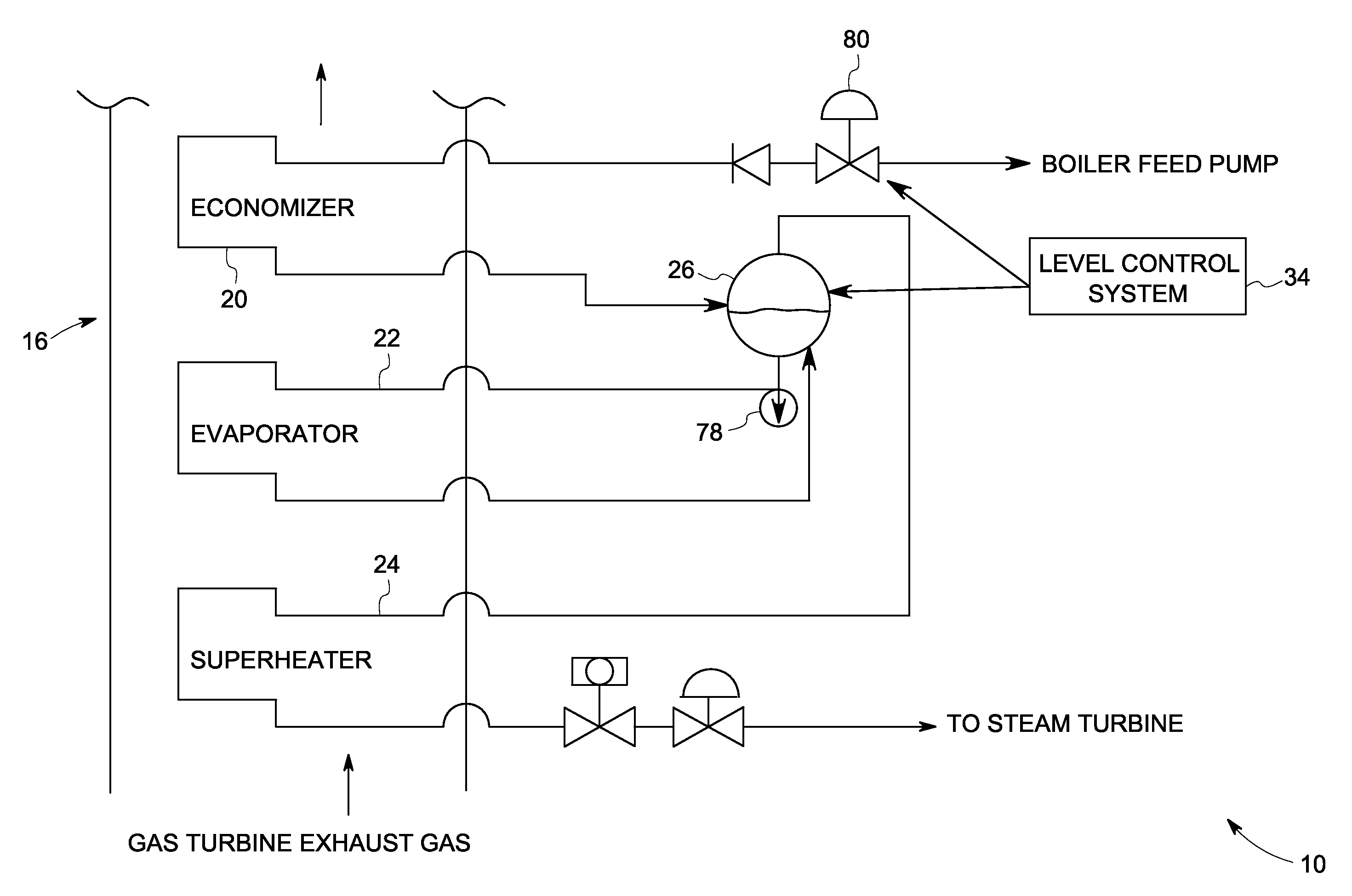
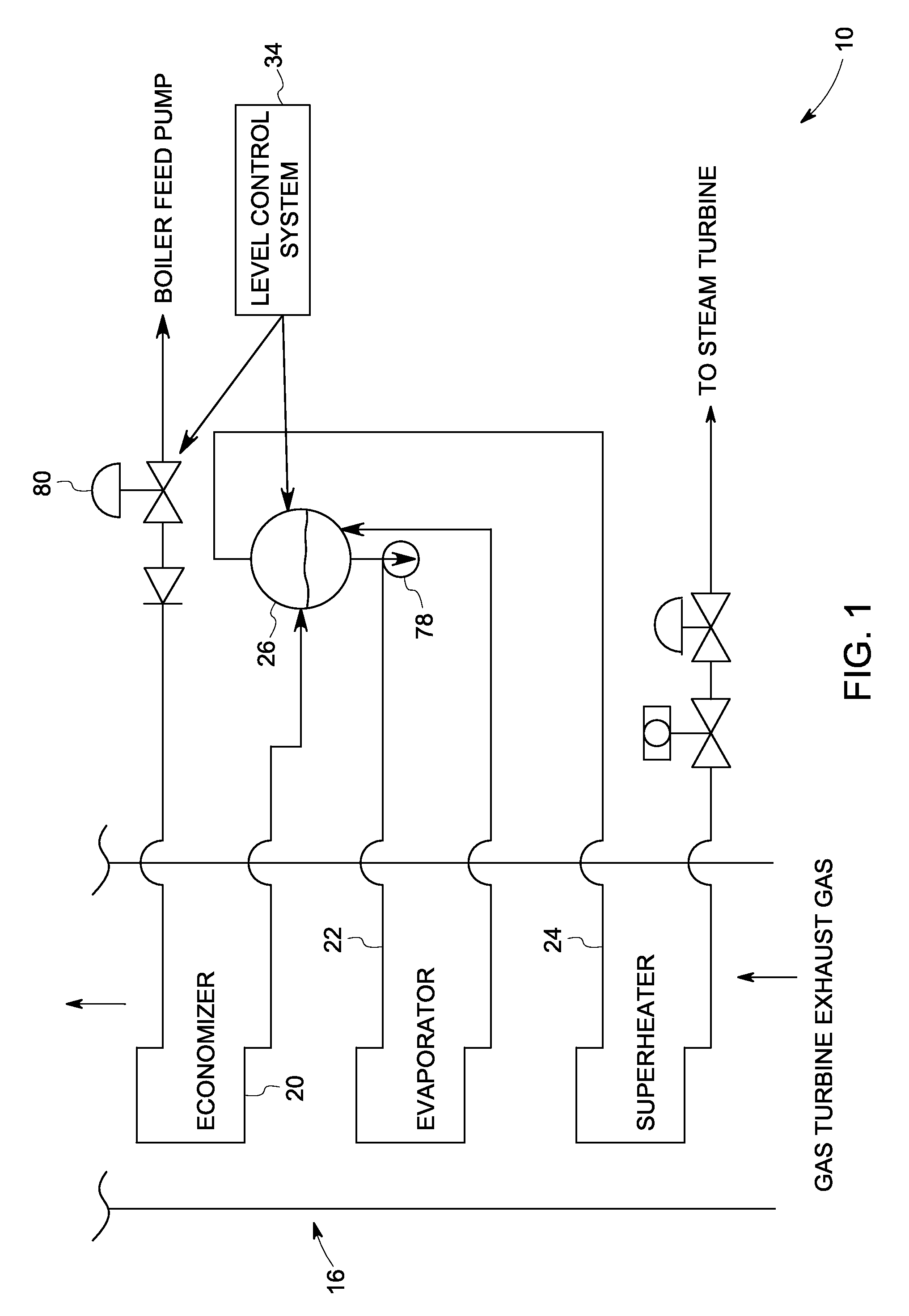
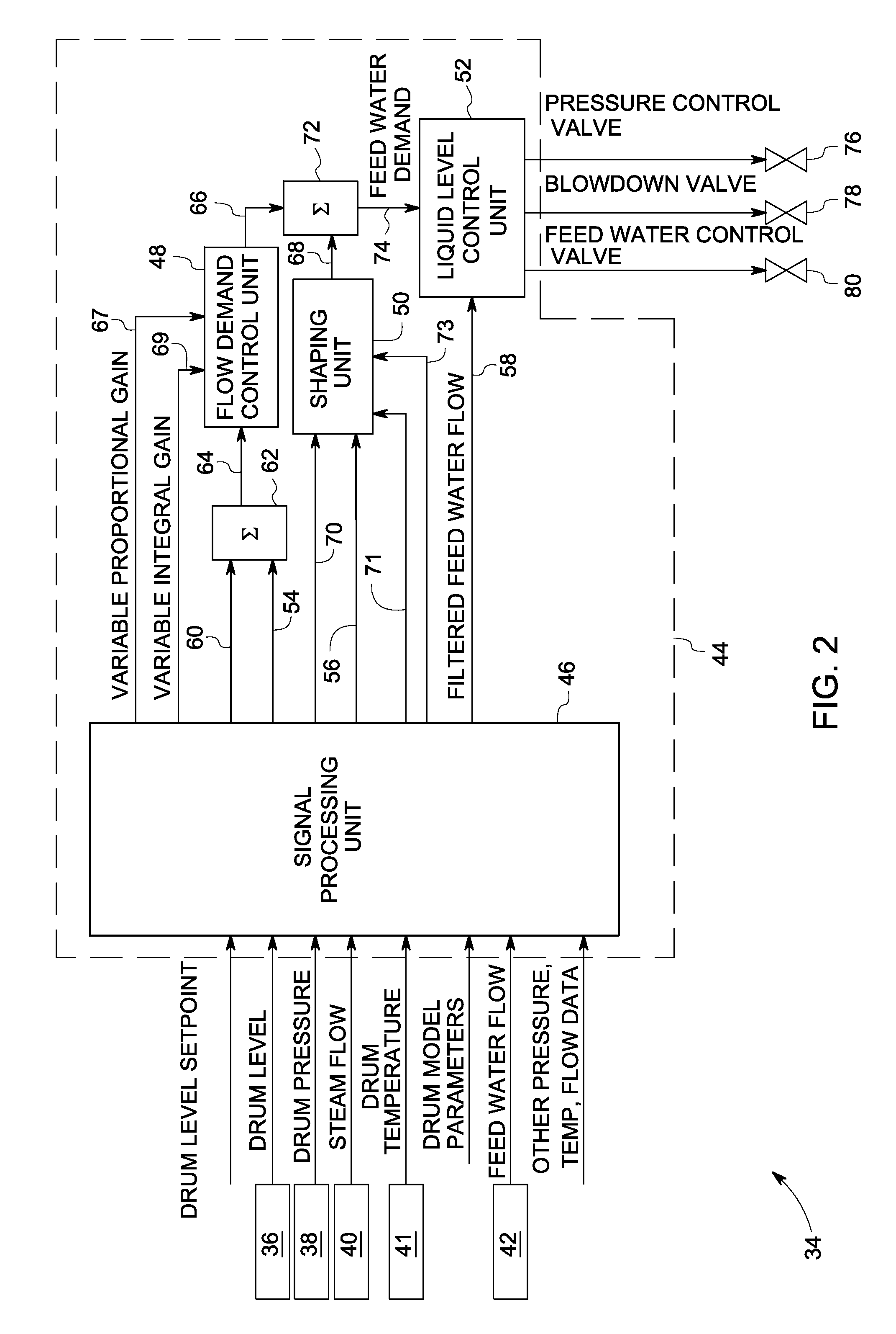
[0013]As discussed in detail below, embodiments of the present invention provide a level control system 34 for controlling a liquid level in a vessel 26 having a two-phase medium i.e. both liquid and gas (FIG. 1). The control system has sensors 36, 38, 40, 41 and 42 provided to measure parameters relating to the vessel including liquid level in the vessel, pressure in the vessel, gas flow rate from the vessel, temperature of the vessel, and feed-liquid flow rate into the vessel (FIG. 2). A signal processing unit 46 receives output signals from sensors and generates a first filtered output signal representative of liquid level in the vessel, a second filtered output signal representative of gas flow rate from the vessel, a third filtered output signal representative of feed-liquid flow rate into the vessel, a fourth filtered output signal representative of pressure in the vessel, and a fifth filtered output signal representative of temperature of the vessel (FIG. 2). A flow demand co...


PUM


Abstract

A system includes sensors configured to measure parameters related to a vessel including liquid level, gas flow rate, pressure in the vessel, temperature of the vessel, and feed-liquid flow rate. A signal processing unit receives sensor output signals and generates a first filtered output signal representative of liquid level, a second filtered output signal representative of gas flow rate, a third filtered output signal representative of feed-liquid flow rate, a fourth filtered output signal representative of vessel pressure, and a fifth filtered output signal representative of vessel temperature. A flow demand control unit receives the first filtered output signal and generates an output signal representative of feed-liquid flow demand. A shaping unit receives the second, fourth, and fifth filtered output signal and generates an output signal representative of shaped gas flow rate as a function of pressure, temperature, or combination thereof in the vessel. A liquid level control unit controls the liquid level within predetermined limits by controlling one or more components based on the output signals from the flow demand control unit, the shaping unit, and the third filtered output signal.

Description

BACKGROUND[0001]The system and method disclosed herein relate generally to controlling liquid level in a vessel and, more specifically, to controlling water level in a drum type boiler in a power plant.[0002]Drum type boilers are the most commonly used boilers in power generation plants. Drum level trips are a frequent cause of trips and disruptions in a power station. In the power generation industry, drum level trips due to drum level control behavior during transient operations are the major cause of disruption in power generation and lead to huge loss of plant availability and revenue.[0003]Control of drum water level is a challenging problem due to complicated dynamics of 2 phase flows, presence of waves, unknown heat and pressure disturbances, and load demands. Maintaining water level within limits is critical, as exceeding the limits will lead to trips or damage the equipment. The drum boiler has to operate in the presence of various unknown pressure and load (thermal) distur...

Claims


Application Information

Patent Timeline
IPC IPC(8): F22D5/26
CPCY02E20/16F01K23/101Y10T137/0374Y10T137/7297
Inventor MEHENDALE, CHARUDATTA SUBHASHNORMAN, BRUCE GORDONKARACA, ERHANKUMAR, RAJEEVA
Owner GENERAL ELECTRIC CO
Learn More